The Builder's Guide.
The LM42P is uncompromising in its component quality. To ensure this technology remains accessible to makers, the mechanical architecture and Bill of Materials (BOM) have been made entirely open source.
System Variants
M1 Architecture
The standard mechanical variant. Designed around custom bushing and housing modules, ideal for makers with standard tooling capabilities.
M2 Architecture
The advanced linear guide variant. This architecture utilizes a dedicated linear rail block for maximum stability and reduced friction.
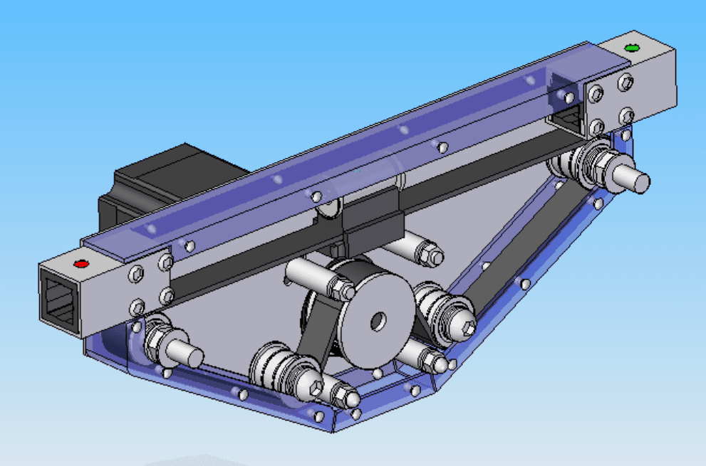
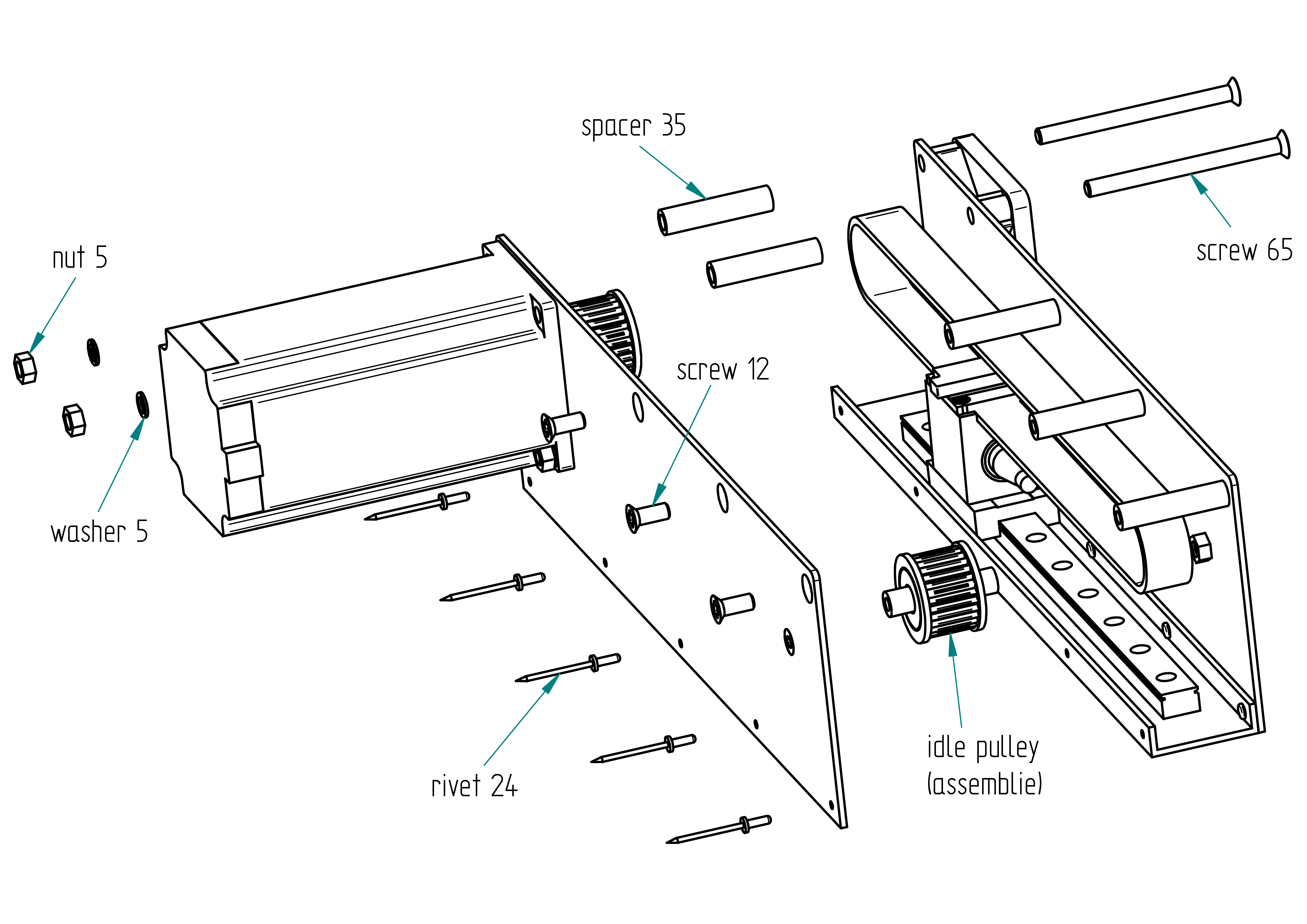
Variant M1: Parts List
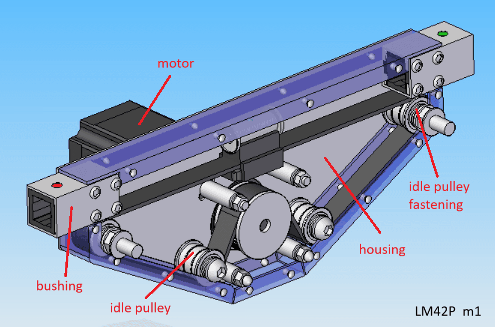
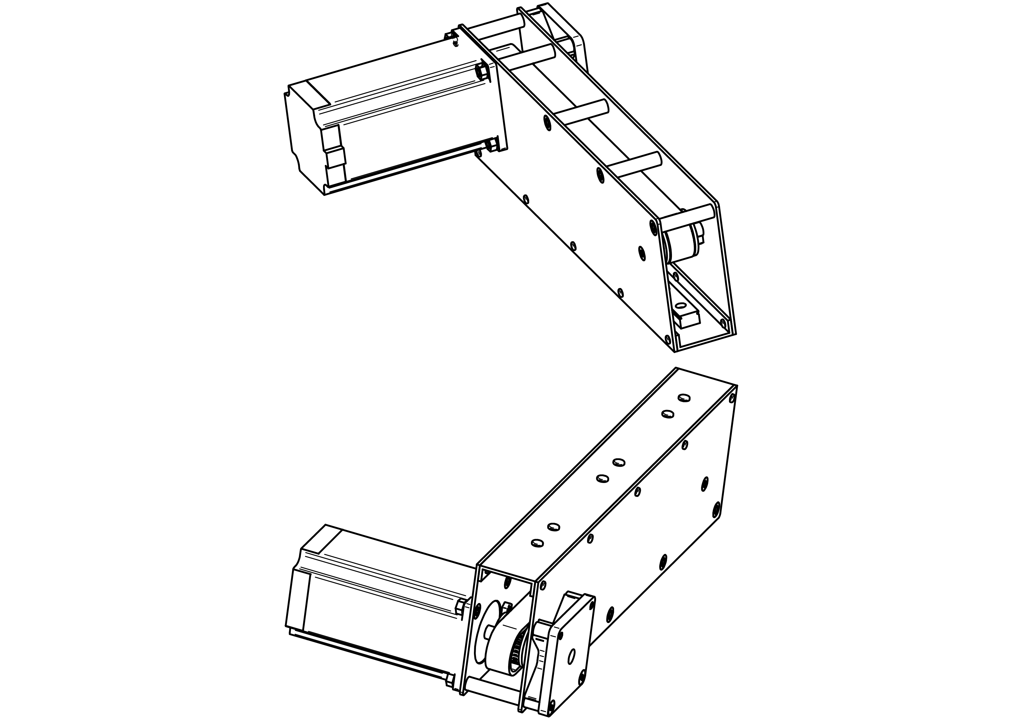
Main Assembly
- ❯1x Housing
- ❯2x Bushing
- ❯1x Junction block
- ❯2x Idle pulley
- ❯2x Idle pulley fastening
- ❯1x Motor
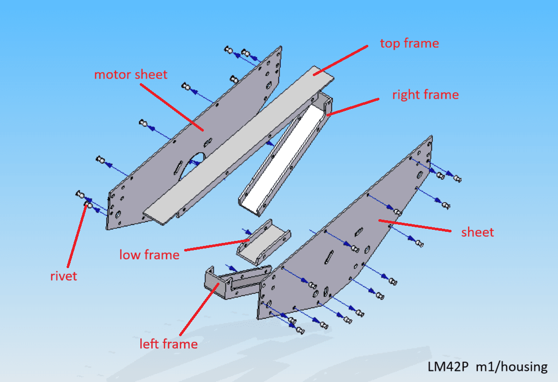
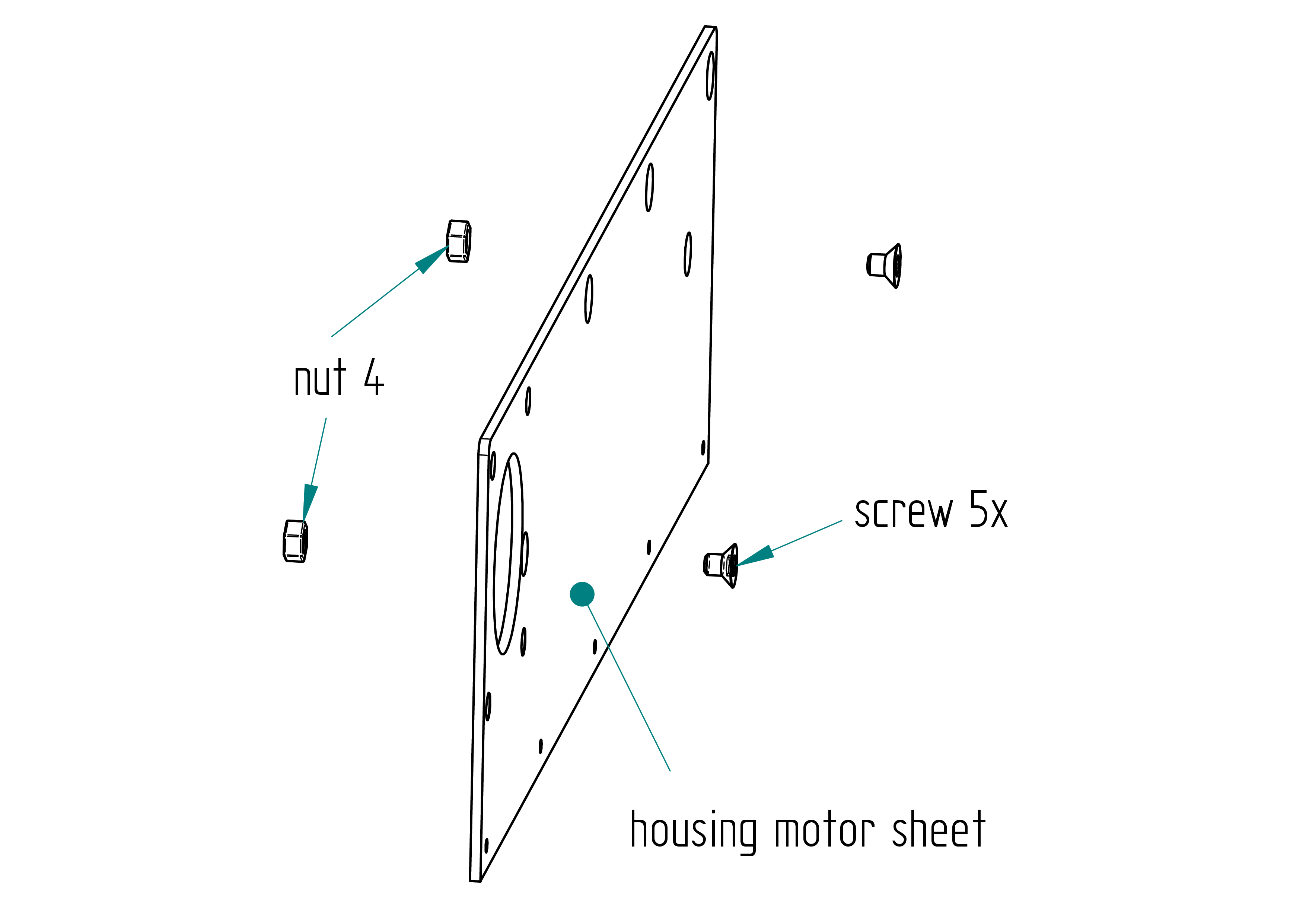
Housing Module
- ❯1x Sheet
- ❯1x Motor sheet
- ❯1x Top frame
- ❯1x Left frame
- ❯1x Right frame
- ❯1x Low frame
- ❯28x Rivet
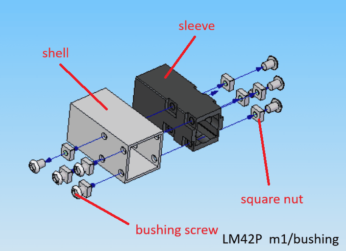
Bushing Module
- ❯2x Shell
- ❯2x Sleeve
- ❯16x Square nut
- ❯16x Screw
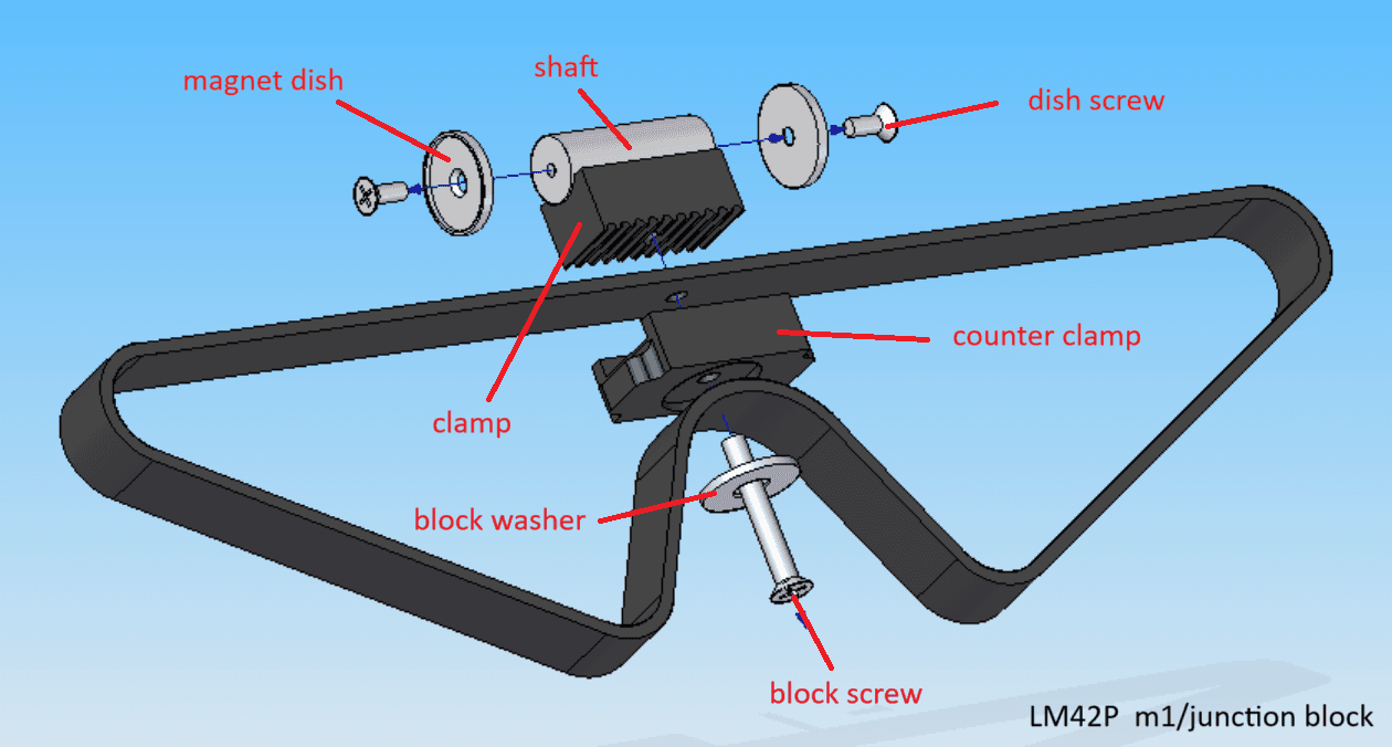
Junction Block
- ❯1x Shaft
- ❯2x Magnet dish
- ❯2x Dish screw
- ❯1x Clamp
- ❯1x Counter clamp
- ❯1x Block washer
- ❯1x Block screw
- ❯1x Belt
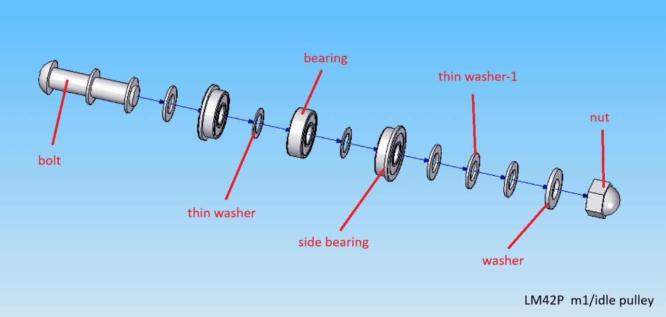
Idle Pulley
- ❯2x Bolt
- ❯4x Thin washer
- ❯2x Bearing
- ❯4x Side bearing
- ❯12x Thin washer-1
- ❯2x Washer
- ❯2x Nut
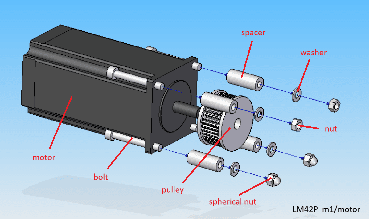
Motor Module
- ❯1x Motor
- ❯1x Pulley
- ❯4x Spacer
- ❯4x Bolt
- ❯4x Washer
- ❯2x Nut
- ❯2x Spherical nut
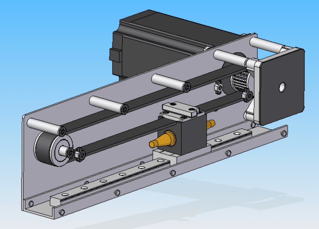
Variant M2: Parts List

Main Assembly
- ❯1x Housing
- ❯2x Linear guide
- ❯1x Block
- ❯1x Idle pulley
- ❯1x Attachment
- ❯1x Motor
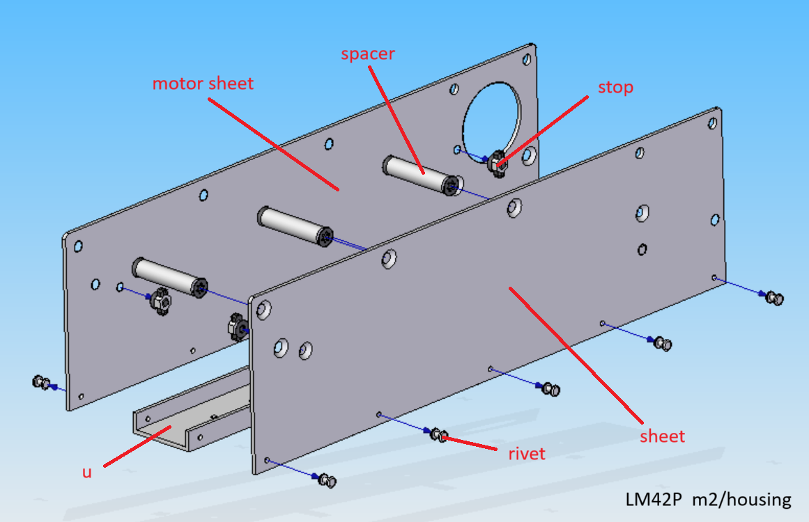
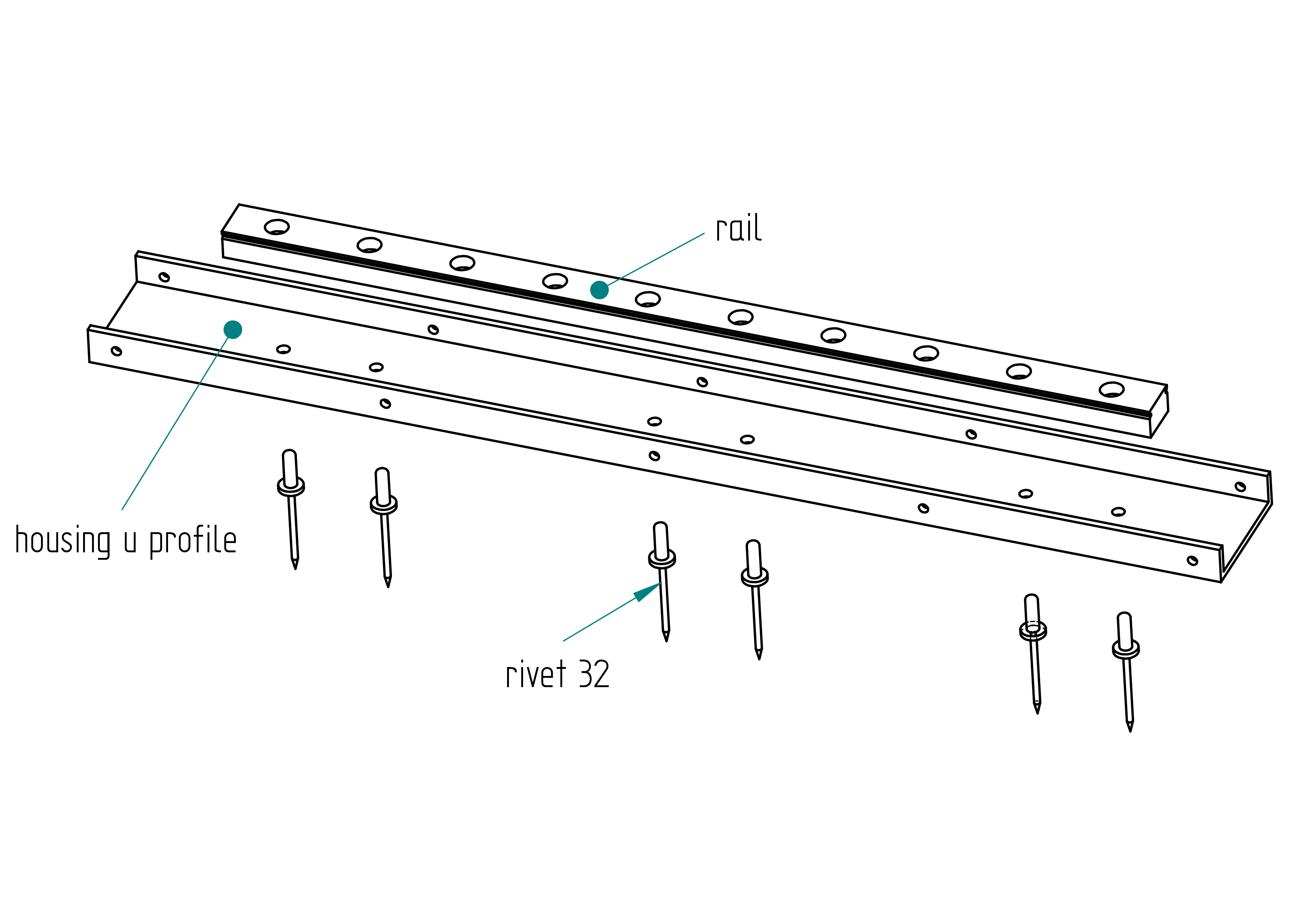
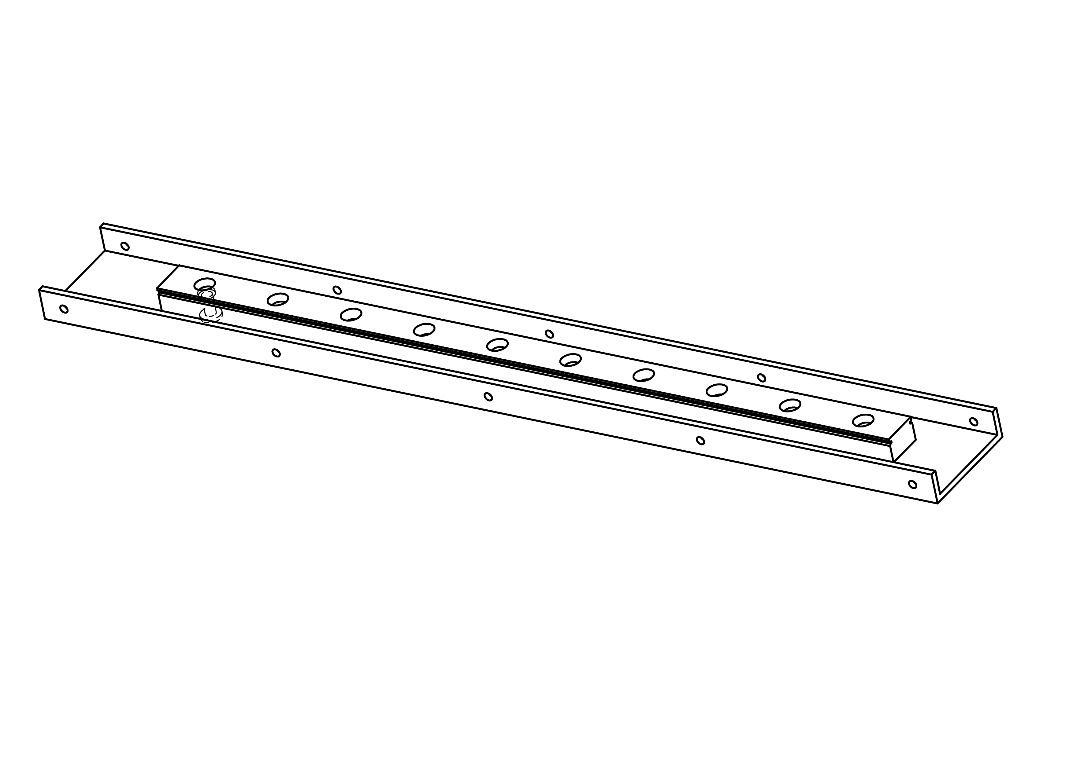
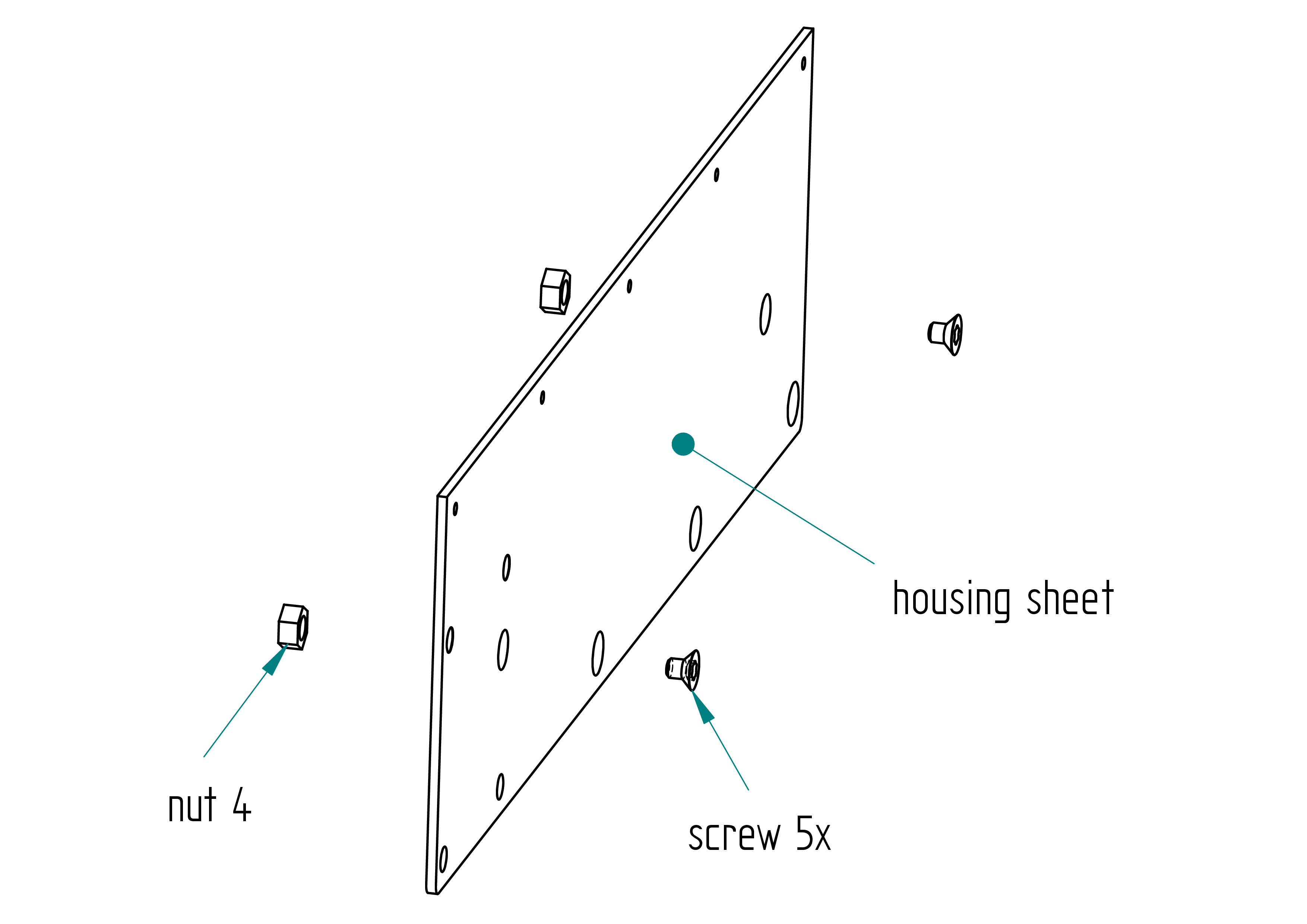
Housing Module
- ❯1x Sheet
- ❯1x Motor sheet
- ❯1x U-Profile
- ❯3x Spacer
- ❯5x Rivet
- ❯4x Stop
Linear Guide
- ❯1x Rail
- ❯1x Slider
- ❯6x Rivet
Junction Block
- ❯1x Junction block
- ❯2x Male junction
- ❯1x Glue
- ❯1x Clamp
- ❯1x Stop
- ❯4x Screw
- ❯1x Belt
Attachment Module
- ❯1x Plate
- ❯1x Stop nut
- ❯1x Nut
- ❯1x Washer
- ❯4x Spacer
- ❯4x Screw
- ❯1x Grip

Motor Module
- ❯1x Motor
- ❯1x Pulley
- ❯2x Spacer
- ❯2x Spacer screw
- ❯4x Screw
- ❯4x Nut
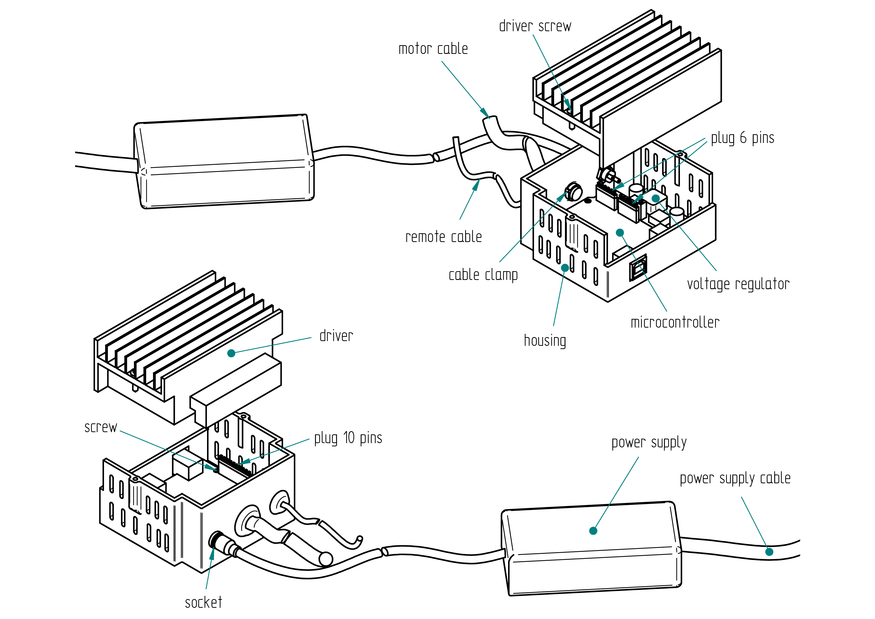
Core Electronics
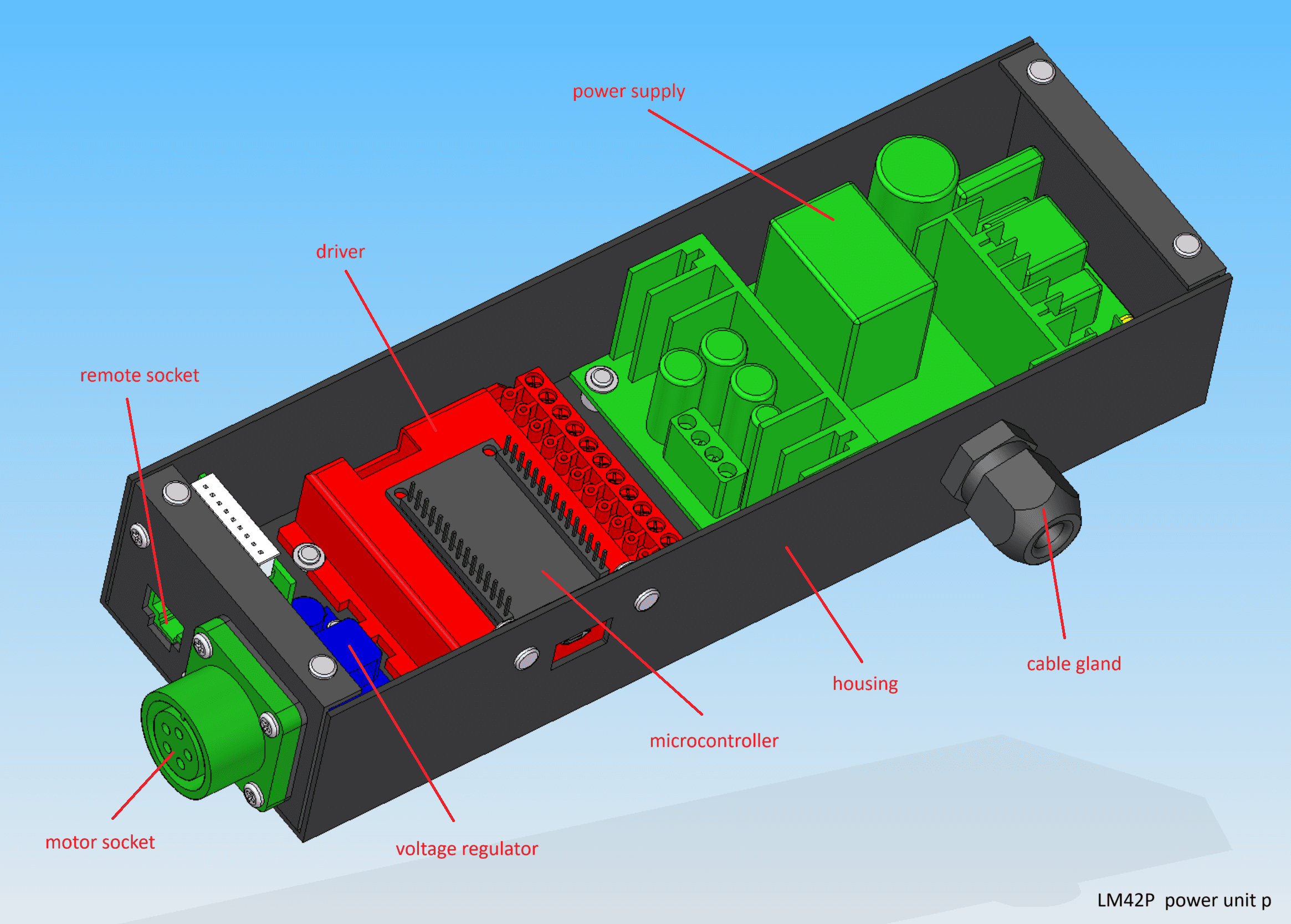
Power Unit P
- ❯1x Housing
- ❯1x Power supply
- ❯1x Driver (Gecko/TB6600)
- ❯1x Microcontroller (ESP32/Uno)
- ❯1x Voltage regulator
- ❯1x Motor socket
- ❯1x Remote socket
- ❯1x Cable gland
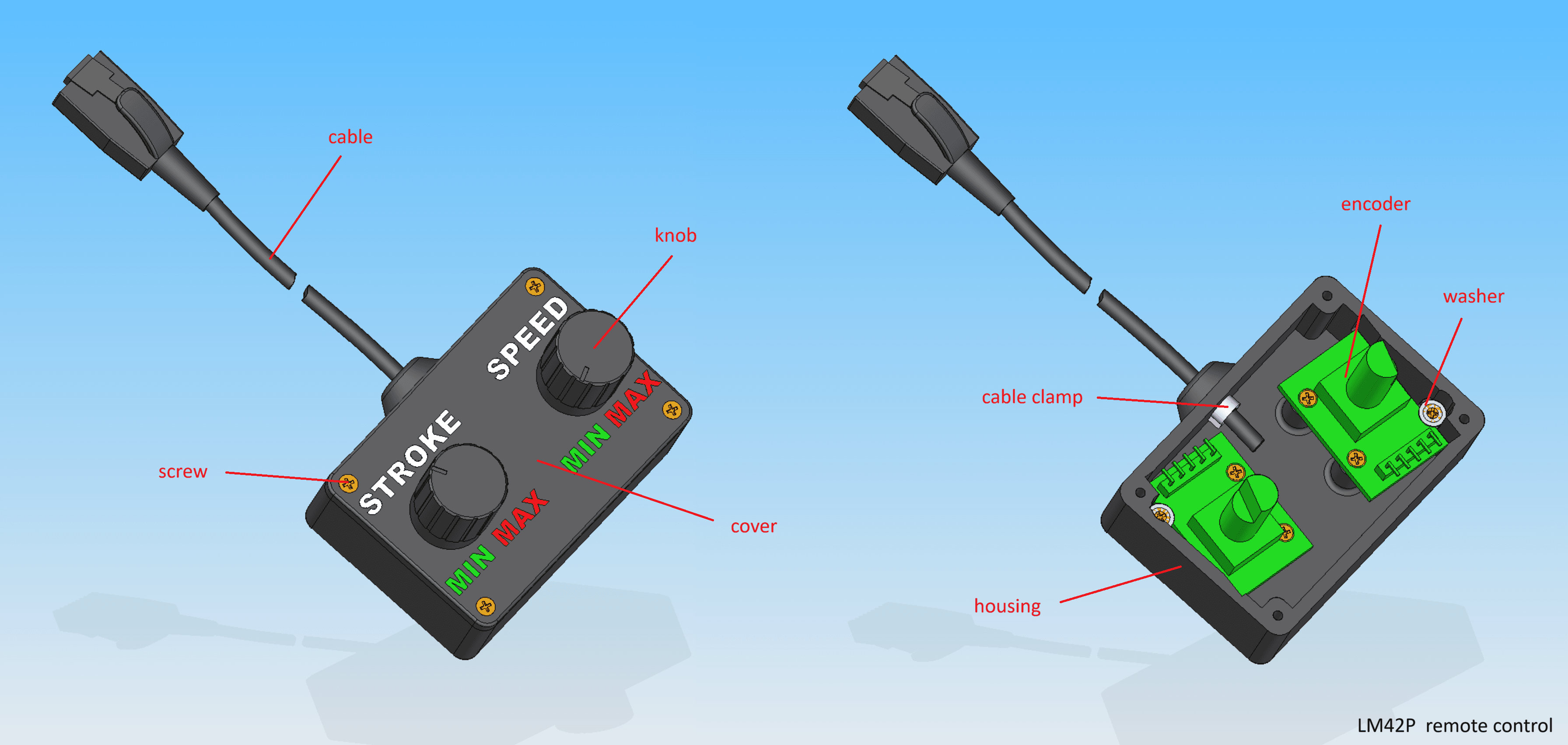
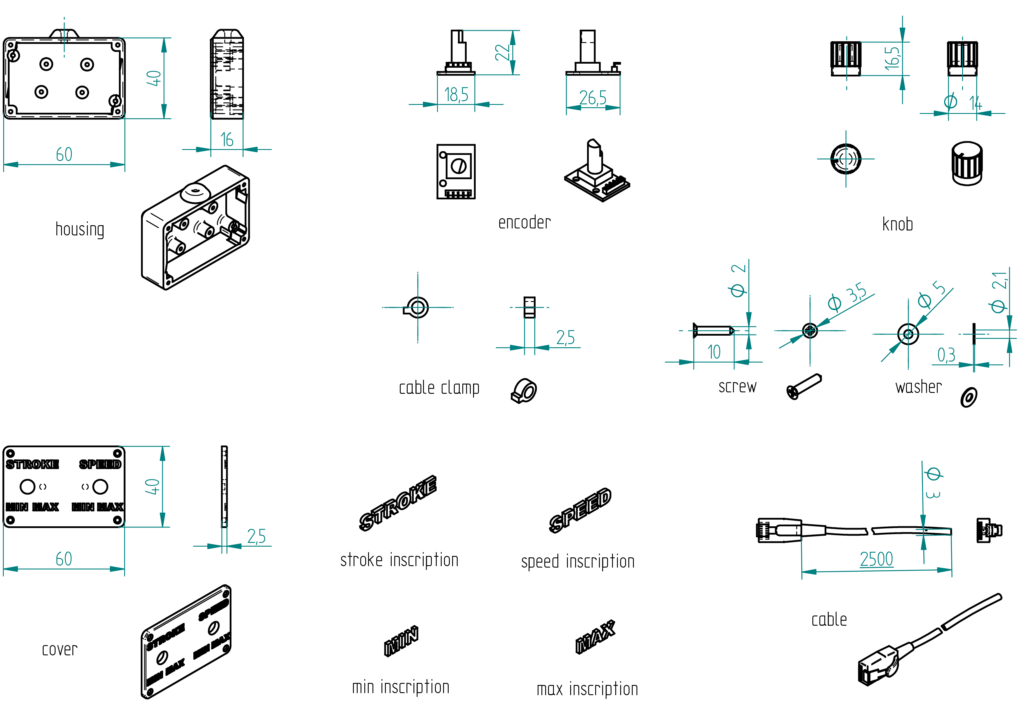
Remote Control
- ❯1x Housing
- ❯1x Cover
- ❯2x Encoder
- ❯2x Knob
- ❯1x Cable
Complete Builder's Manual
Download DIY Build GuideDIY
This document is provided solely for the purpose of building your own personal machine. You are welcome to read it for educational use only. Any commercial use of this document is strictly prohibited. Copying any part of this project (including photos, videos, or plans) is not allowed without prior permission from me.
LM42P cannot be held responsible for any malfunction of the machine that may result in injury. You use this machine entirely at your own risk and responsibility.
Below you will find information on how to obtain an LM42P. Currently, two variants are available:
- M1
- M2
Before you begin building your machine, please take note of the following important information :
- For the 3D-printed parts, all files are located in the directory
named
3d-print-files, which is inside the parent directory named after the corresponding part. - All part names are marked in bold.
- Apply threadlock to the screws.
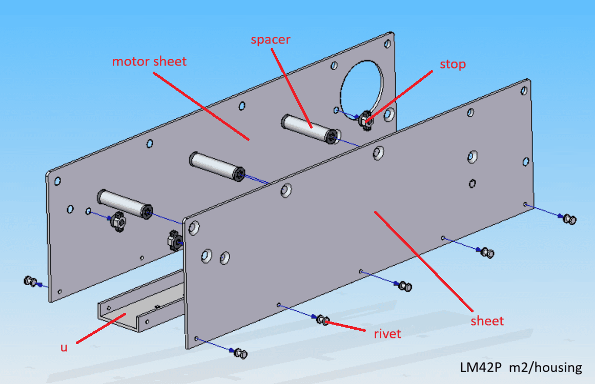
m2
housing
Parts list
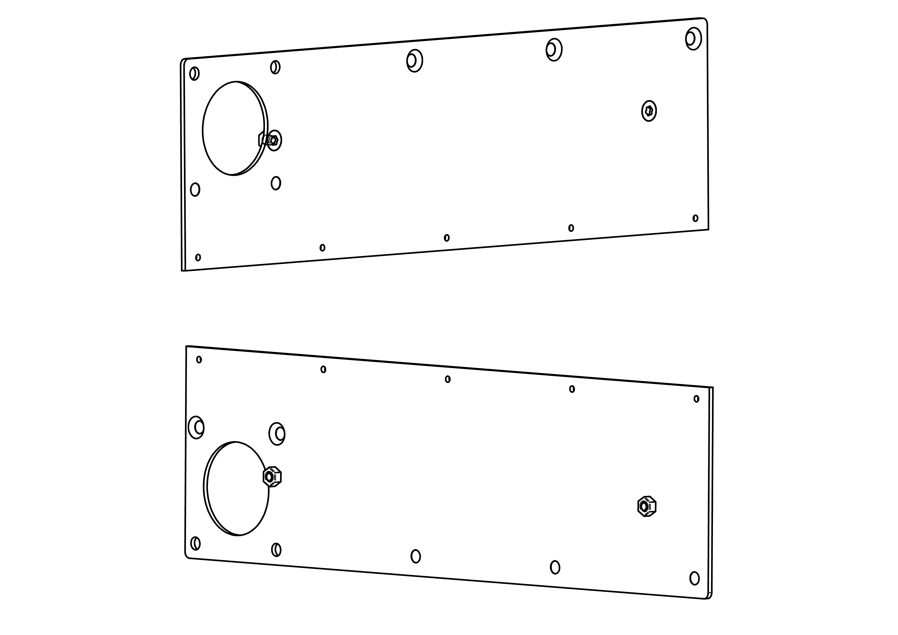
| Qty | Part | Description | Material |
|---|---|---|---|
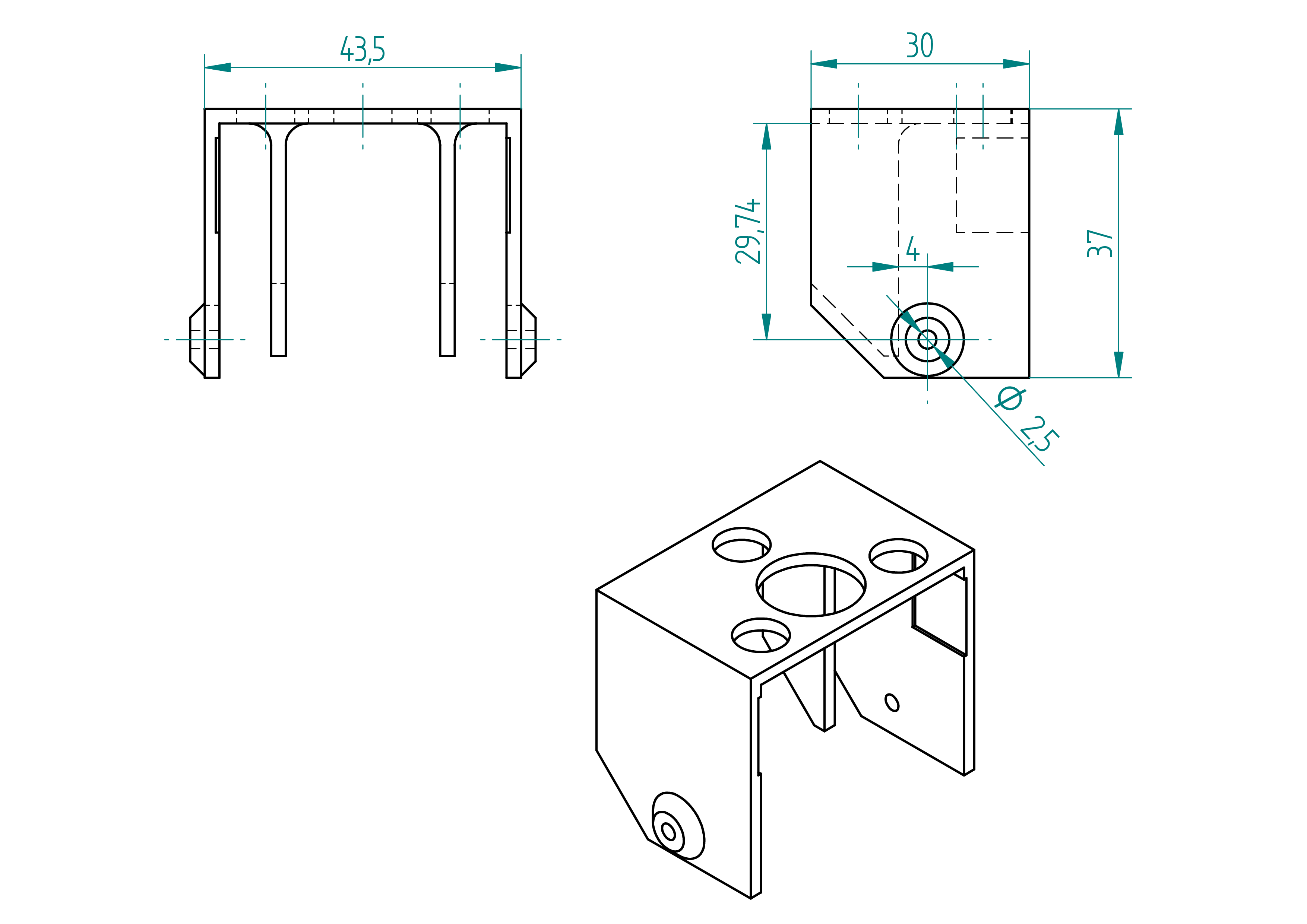
| 1 | u | 10x35x250 | aluminium |
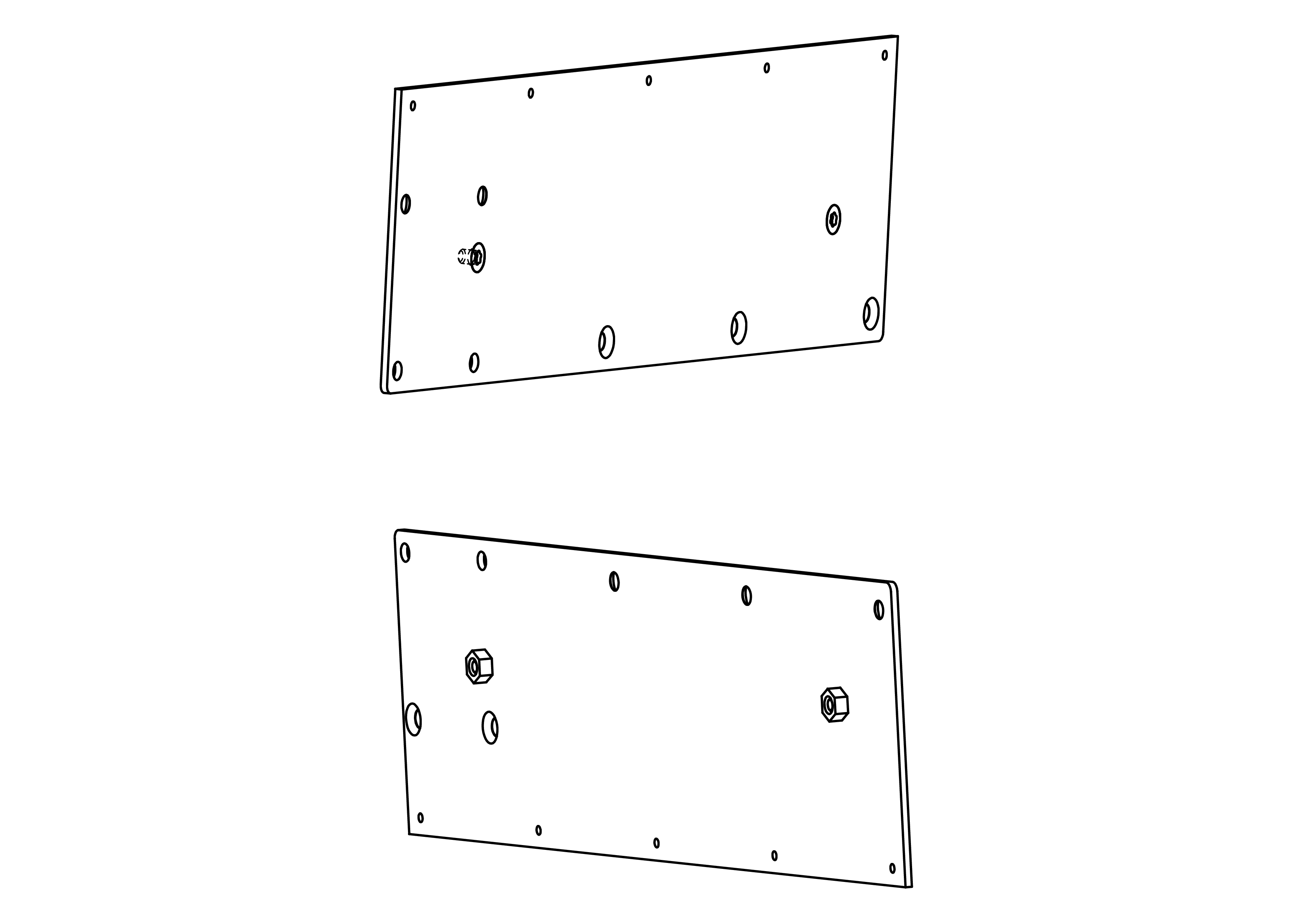
| 1 | sheet | 86x305x2 | aluminium |
| 1 | motor sheet | 86x305x2 | aluminium |
| 4 | stop | 13.7x33x4 | aluminium |
| 3 | spacer | see section spacer | - |
| 10 | rivet | 2.4 x 8 mm | aluminium |
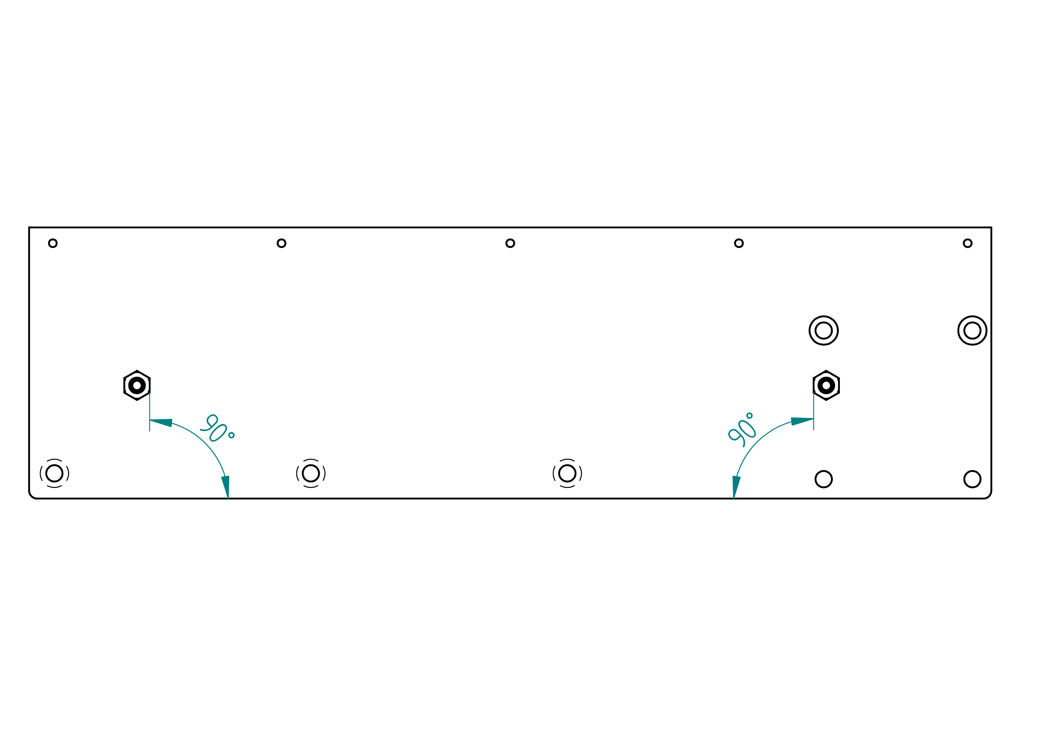
sheet
This section describes the manufacturing process for the part called sheet.
Drawing
.
Required Tools and Components
Below is the list of materials required to produce the part named sheet.
- 1x sheet dimensions : 86x305x2 material : aluminium ;
- 1x steel rule ;
- 1x file ;
- 1x drillator see section drillator , p. ;
- 1x drillator-m see section drillator-m , p. ;
- 4x clamp ;
- 2x 2.5 mm drill bit ;
- 1x 4.2 mm drill bit ;
- 1x 5.2 mm drill bit ;
- 1x chamfering tool ;
- 1x drill press.
Manufacturing Instructions
- use a file to remove all sharp edges ;
- carefully determine which face requires protection before proceeding ;
- align and clamp the drillator-m, using the top-left corner as a reference, this is important for proper alignment ;
- center punch all holes using a 2.5 mm drill bit ;
- remove the drillator-m ;
- using the same drill bit, drill the two holes positioned at the far-left edge, one at the uppermost and one at the lowermost position ;
- using two 2.5 mm drill bits, align and clamp the drillator ;
- center punch all holes ;
- remove the drillator ;
- drill all holes ;
- chamfer all holes (use a screw to check the chamfer depth) ;
- use a file to create both R 2.5 mm radii ;
- remove the protective film or masking.
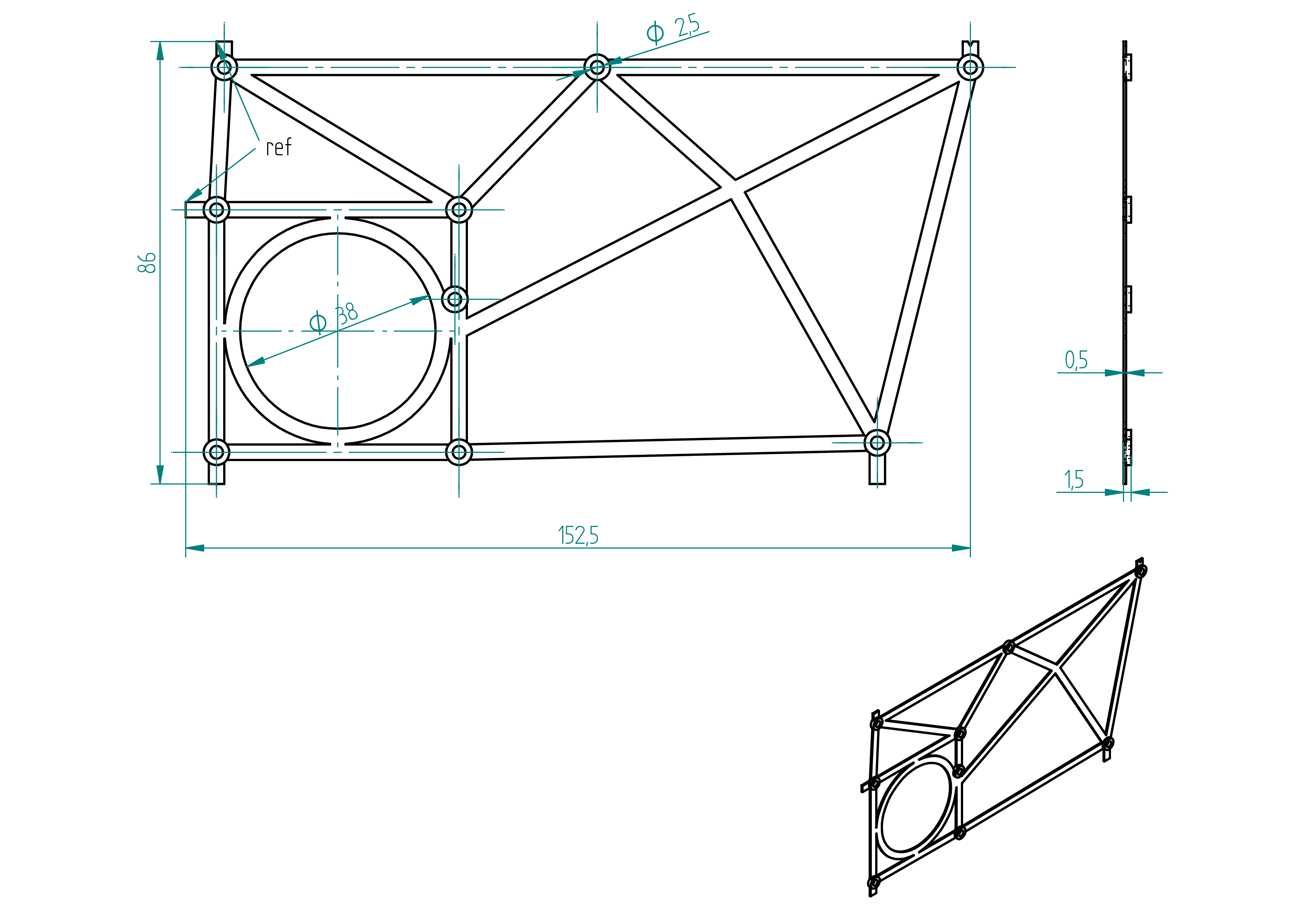
motor-sheet
This section describes the manufacturing process for the part called motor-sheet.
Drawing
.
Required Tools and Components
Below is the list of materials required to produce the part named motor-sheet.
- 1x sheet dimensions : 86x305x2 material : aluminium ;
- 1x flat/convex file ;
- 1x drillator see section drillator , p. ;
- 1x drillator-m see section drillator-m , p. ;
- 1x scribe ;
- 4x clamp ;
- 2x 2.5 mm drill bit ;
- 1x 4.2 mm drill bit ;
- 1x 5.2 mm drill bit ;
- 1x jigsaw ;
- 1x chamfering tool ;
- 1x drill press.
Manufacturing Instructions
- use a file to remove all sharp edges ;
- carefully determine which face requires protection before proceeding ;
- align and clamp the drillator-m, using the top-left corner as a reference, this is important for proper alignment ;
- using a scriber, mark the outline of the 38 mm diameter hole ;
- center punch all holes using a 2.5 mm drill bit ;
- remove the drillator-m ;
- using the same drill bit, drill the two holes positioned at the far-left edge, one at the uppermost and one at the lowermost position ;
- using two 2.5 mm drill bits, align and clamp the drillator ;
- center punch all holes ;
- remove the drillator ;
- drill all holes ;
- chamfer all holes (use a screw to check the chamfer depth) ;
- use a file to create both R 2.5 mm radii ;
- using a jigsaw, cut as close as possible to the 38 mm diameter outline ;
- Using a flat/convex file, file the 38 mm hole until the motor fits through ;
- remove the protective film or masking.
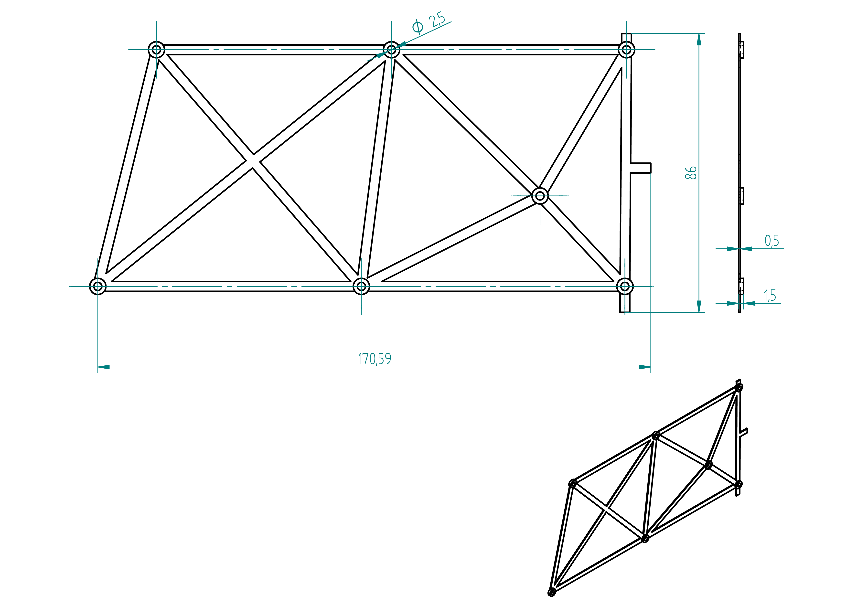
u
This section describes the manufacturing process for the part called u.
Drawing
.
Required Tools and Components
Below is the list of materials required to produce the part named u.
- 1x square tube dimension : 35x35x2x305 material : aluminium ;
- 1x gauge minimum length: 305 mm ;
- 1x try square ;
- 1x steel rule ;
- 1x scriber ;
- 1x hand saw ;
- 1x perpendicaltor ;
- 1x file ;
- 1x rail (see section linear-guide , p. ) ;
- 2x clamp ;
- 1x 3.5 mm drill bit ;
- 1x 3.3 mm drill bit ;
- 1x 2.5 mm drill bit ;
- 1x chamfering tool ;
- 1x drill press.
Manufacturing Instructions
- scribe a line with a scriber, leaving approximately 0.3 mm of extra material beyond the final total length ;
- cut the square tube to length using a handsaw and a try square ;
- use the perpendiculator to ensure both ends are square ;
- scribe two lines using the scriber, each about 0.3 mm from the edge of the squared square tube ;
- cut the square tube along the scribed lines using the handsaw ;
- use a file to clean the cuts and chamfer the edges ;
- clamp the rail in the correct position using a gauge (make sure it’s centered), ;
- mark the positions of the six 3.3 mm holes using a 3.5 mm drill bit to center punch ;
- drill the six holes using a 3.3 mm drill bit (do not drill the 2.5 mm holes yet—those will be drilled with the sheets) ;
- chamfer the six holes using a chamfering tool ;
- clamp the sheet in place ;
- center punch the five holes using a 2.5 mm drill bit ;
- clamp the motor sheet ;
- center punch the five holes using a 2.5 mm drill bit ;
- drill all ten holes using a 2.5 mm drill bit ;
- chamfer the six holes using a chamfering tool.
drillator
This section describes the manufacturing process for the part called drillator.
If your 3D printer has a large enough build volume, you can print the drillator and drillator-m in one piece, which improves alignment accuracy.
Drawing
.
Required Tools and Components
Below is the list of materials required to produce the part named drillator.
- 1x 3d printer ;
- 1x PLA ;
- 1x file ;
- 1x drill ;
- 1x 2.5 mm drill bit.
Manufacturing Instructions
- 3D print the part using the files located in the
3d-print-filesdirectory ; - chamfer the edges using a file ;
- drill the 2.5 mm holes using a 2.5 mm drill bit and a drill.
drillator-m
If your 3D printer has a large enough build volume, you can print the drillator and drillator-m in one piece, which improves alignment accuracy.
Drawing
.
Required Tools and Components
Below is the list of materials required to produce the part named drillator.
- 1x 3d printer ;
- 1x PLA ;
- 1x file ;
- 1x drill ;
- 1x 2.5 mm drill bit.
Manufacturing Instructions
- 3D print the part using the files located in the
3d-print-filesdirectory ; - chamfer the edges using a file ;
- drill the 2.5 mm holes using a 2.5 mm drill bit and a drill.
stop
Drawing
.
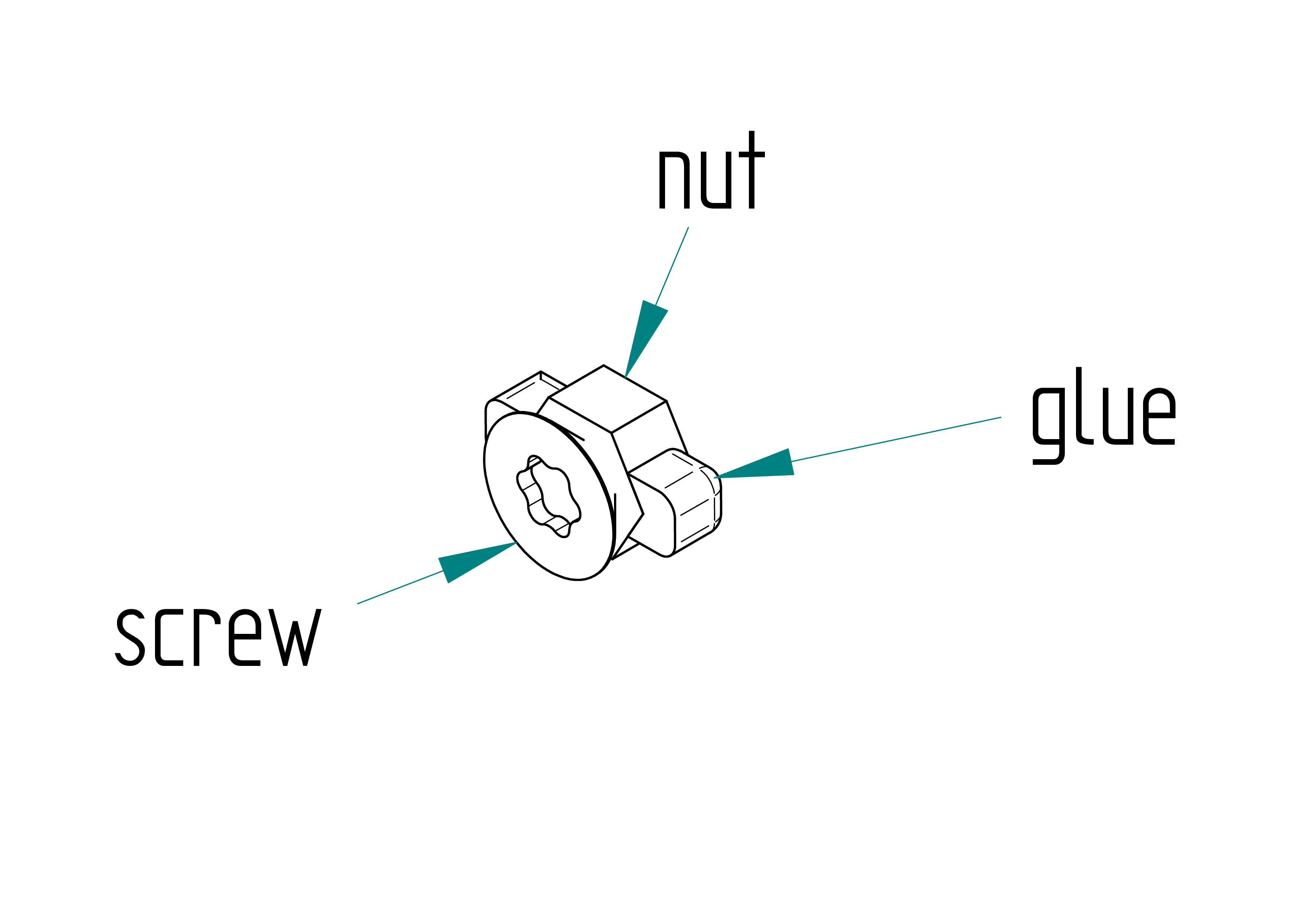
Parts list
| Qty | Part | Description | Material |
|---|---|---|---|
| 4x1=4 | screw | M4 × 6 mm Torx flat head screw | stainless steel |
| 4x1=4 | nut | standard M4 hex nut | stainless steel |
| - | glue | black | Poliflex 444 |
spacer
Drawing
.
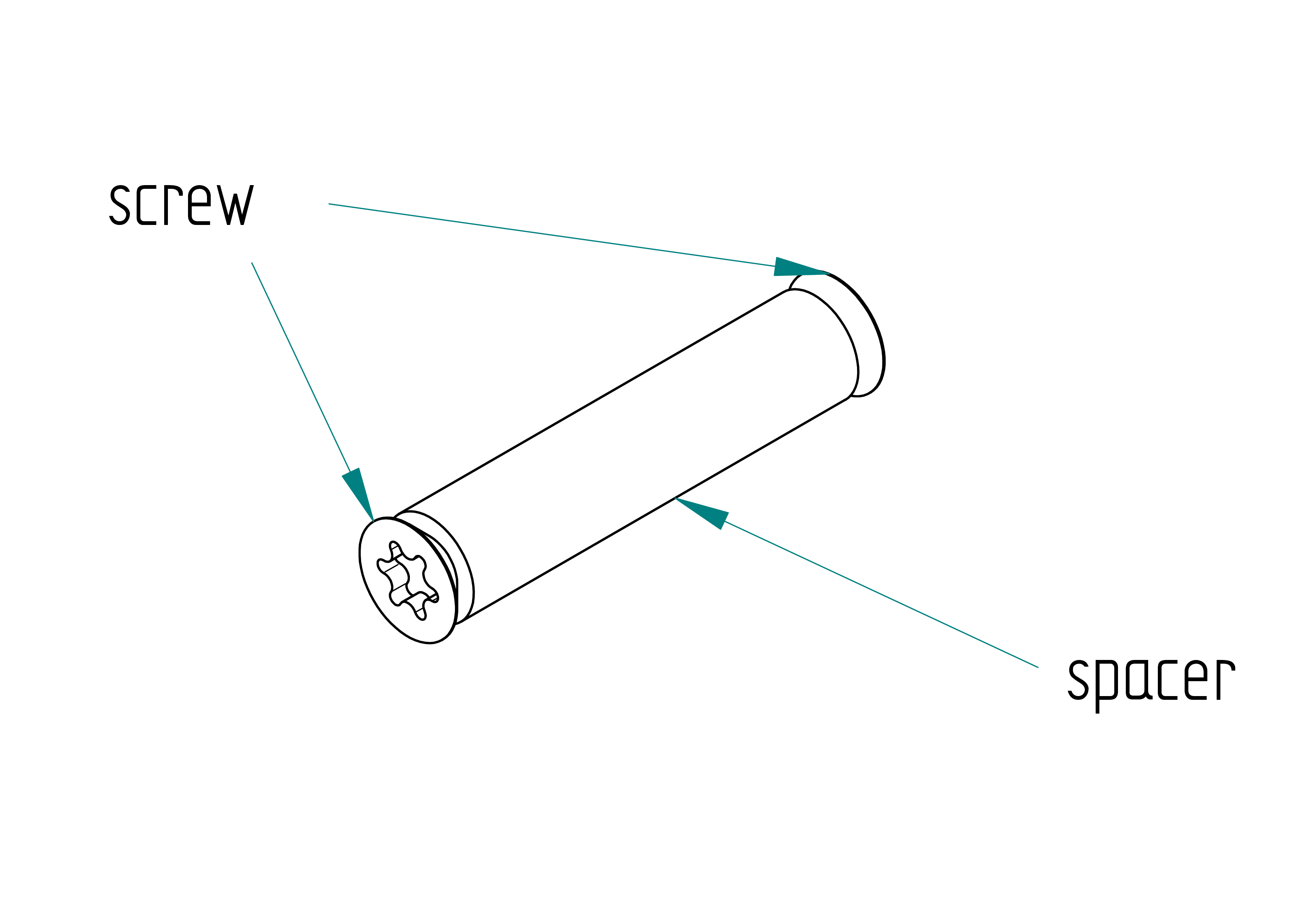
Parts list
| Qty | Part | Description | Material |
|---|---|---|---|
| 3x2=6 | screw | M5 × 12 mm Torx flat head screw | stainless steel |
| 3x1=3 | spacer | M5 x 8 x 35 mm | aluminium |
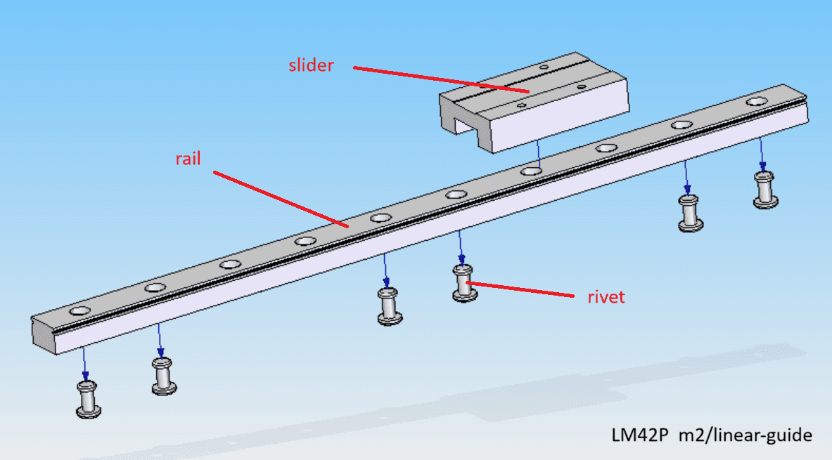
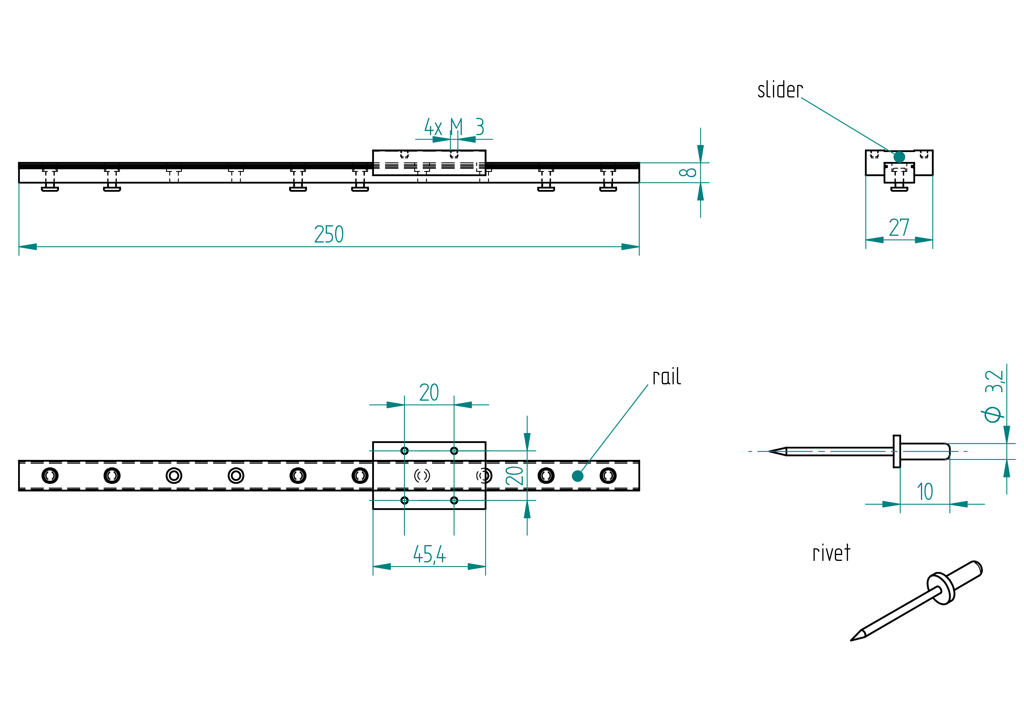
linear guide
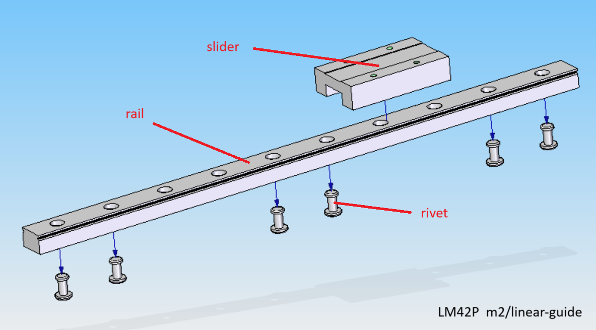
Parts list
| Qty | Part | Description | Material |
|---|---|---|---|
| 1 | rail | MGN12H, length: 250 mm | - |
| 1 | slider | MGN12H, 27 x 45.4 mm | - |
| 6 | rivet | 3.2 x 10 mm | aluminium |
Drawing
.
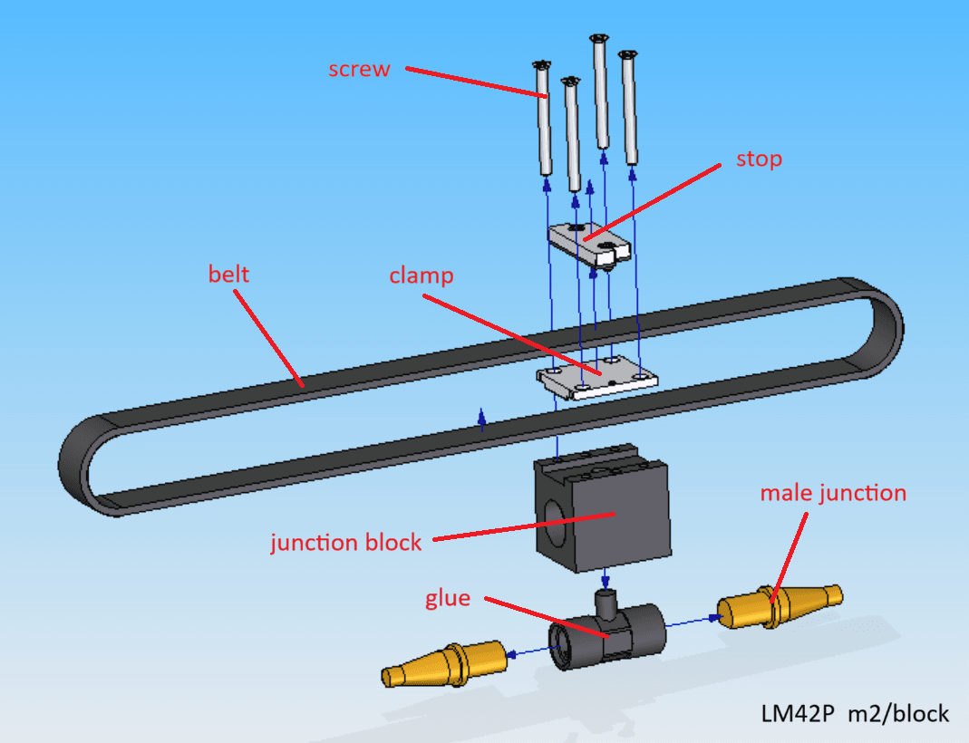
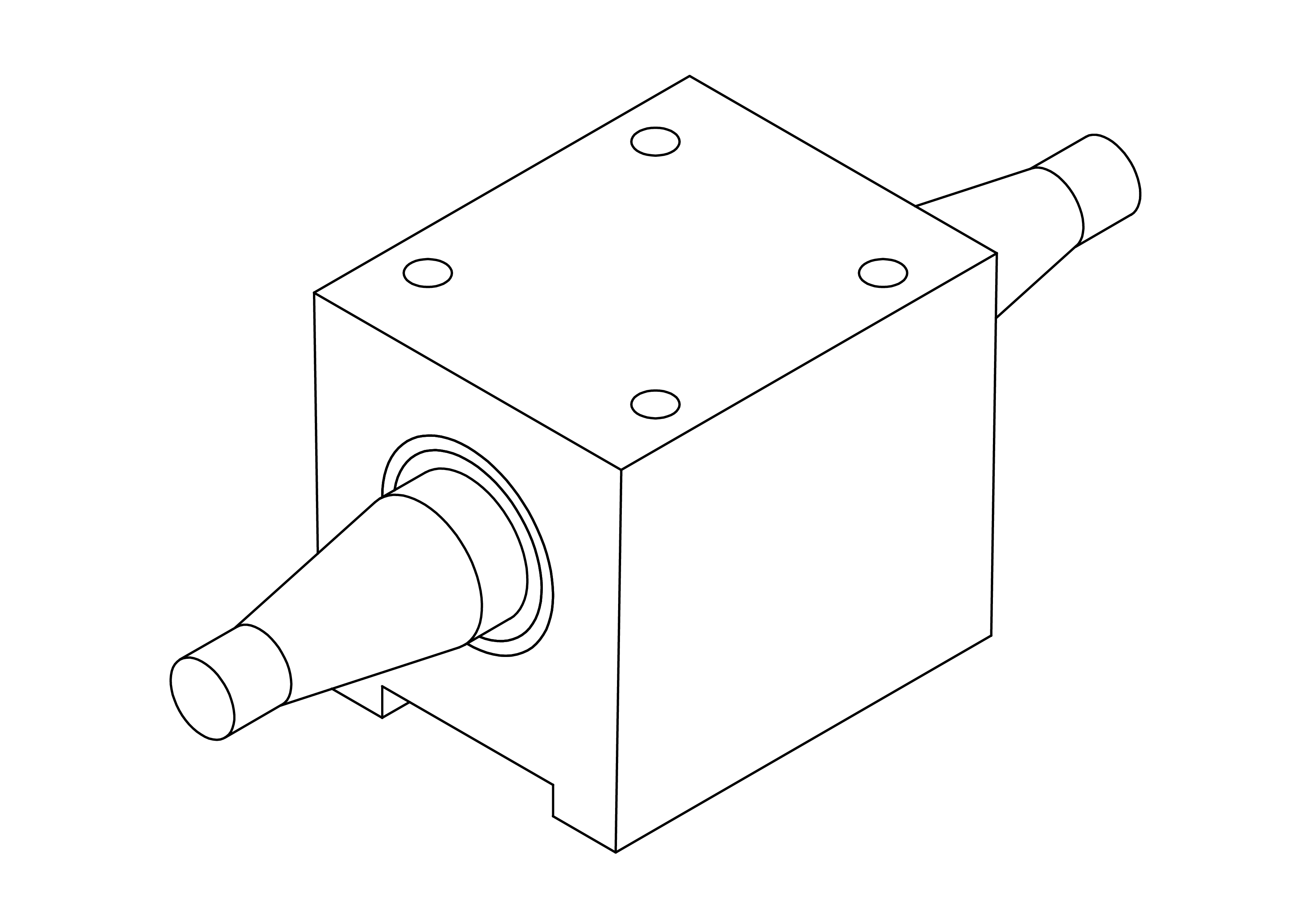
block
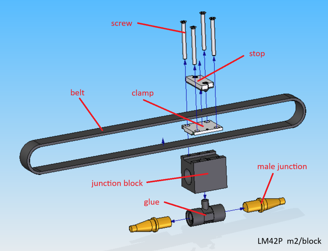
Parts list
| Qty | Part | Description | Material |
|---|---|---|---|
| 1 | junction block | 3D printed | nylon |
| 1 | glue | casted | epoxy |
| 2 | male junction | google : pool cue junction | brass |
| 1 | belt | HTD 3 | - |
| 1 | clamp | HTD 3 | aluminium |
| 1 | stop | subassemblie (see section) | see section stop |
| 4 | screw | M3 × 36 mm flat head screw | stainless steel |
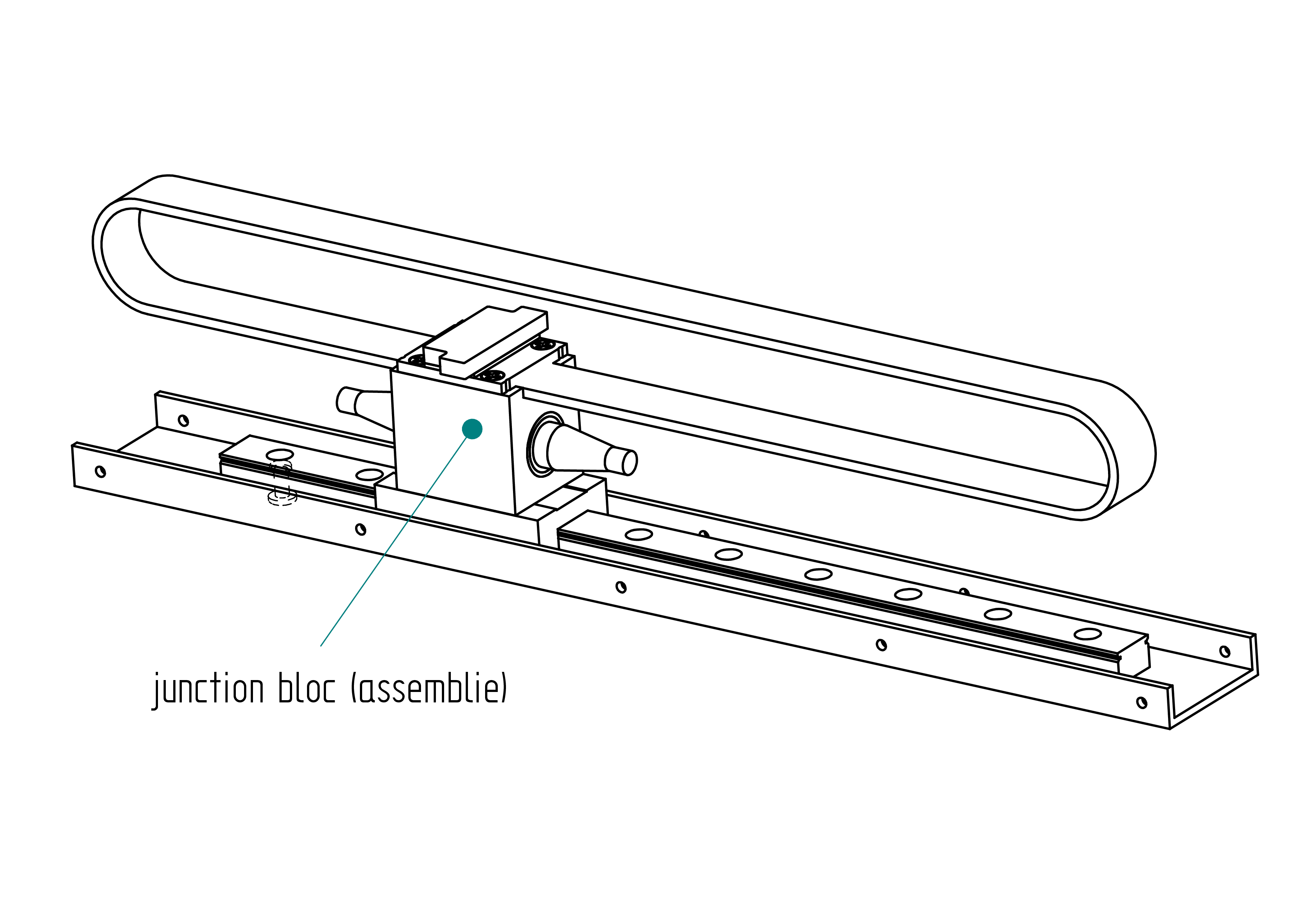
junction block
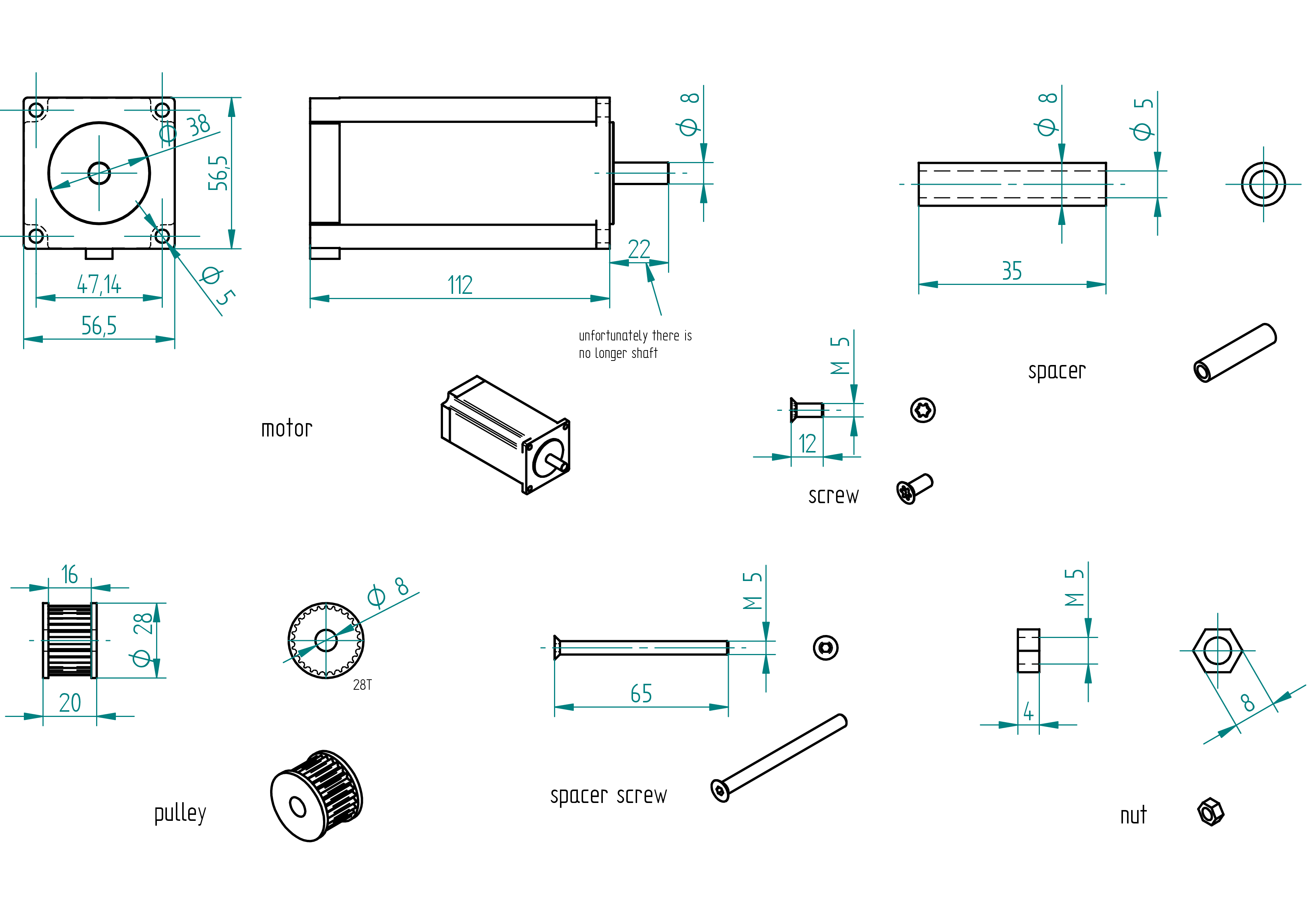
motor
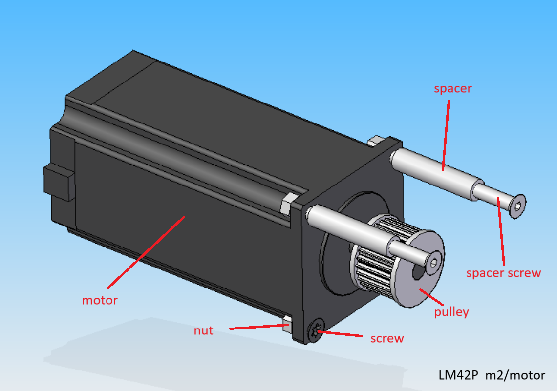
Parts list
| Qty | Part | Description | Material |
|---|---|---|---|
| 1 | motor | Nema 23 4.2A 3N.m 112mm | with cable |
| 1 | pulley | HTD M3 28T 16/8 | aluminium |
| 2 | spacer | M5 x 8 x 35 mm | aluminium |
| 2 | spacer screw | M5 × 65 mm Torx flat head screw | stainless steel |
| 2 | screw | M5 × 12 mm Torx flat head screw | stainless steel |
| 4 | nut | M5 | stainless steel |
Drawing
.
Assembling Instructions
Required Tools and Components
- 1x motor ;
- 1x pulley ;
- 1x spacer ;
- 1x adjustable reamer, diameter 8 mm ;
- 1x sandpaper ;
- 1x acetone.
- 1x shaft glue (Loctite 238) ;
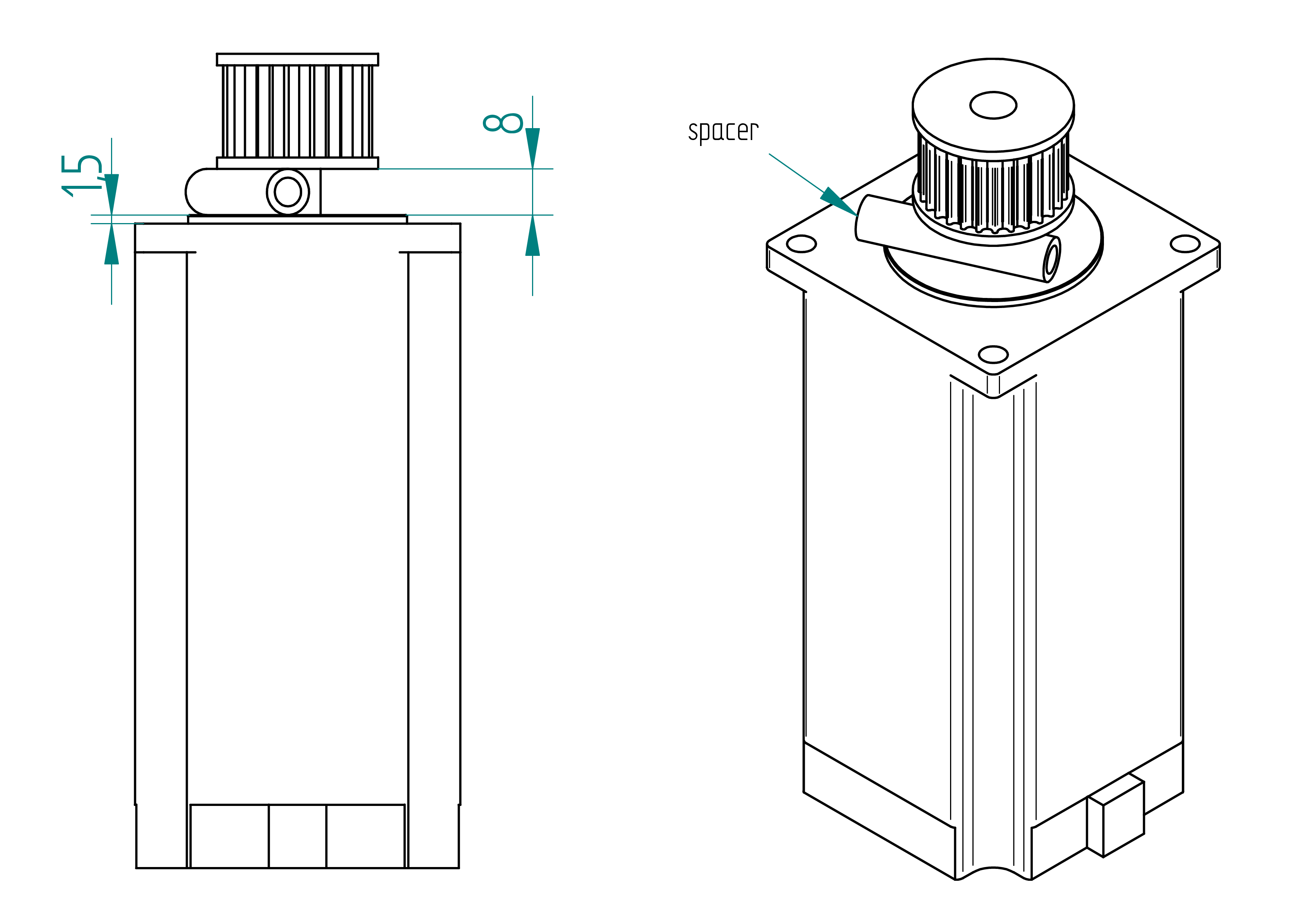
- Test the pulley on the motor shaft.\ There should be a between them (for the shaft glue).
- If there is no gap :
- Use an adjustable reamer (diameter 8 mm) to carefully enlarge the hole in the pulley until the pulley fits with a slight gap.
- Clean the shaft and the pulley with acetone.
- Apply shaft glue to the shaft.
- Press the pulley onto the spacer, using a spacer to ensure correct positioning (.
- Let it cure for 4 hours.
idle pulley
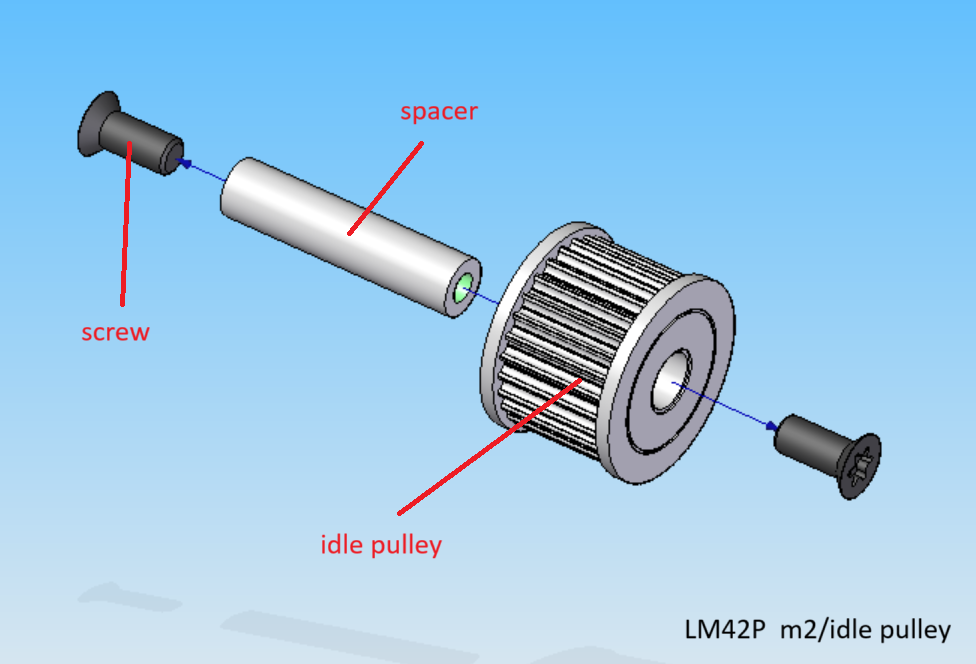
Parts list
| Qty | Part | Description | Material |
|---|---|---|---|
| 1 | idle pulley | HTD3 28T / 8 | Aluminium |
| 2 | screw | M5 × 12 mm Torx flat head screw | stainless steel |
| 1 | spacer | M5 x 8 x 35 mm | Aluminium |
Drawing
.
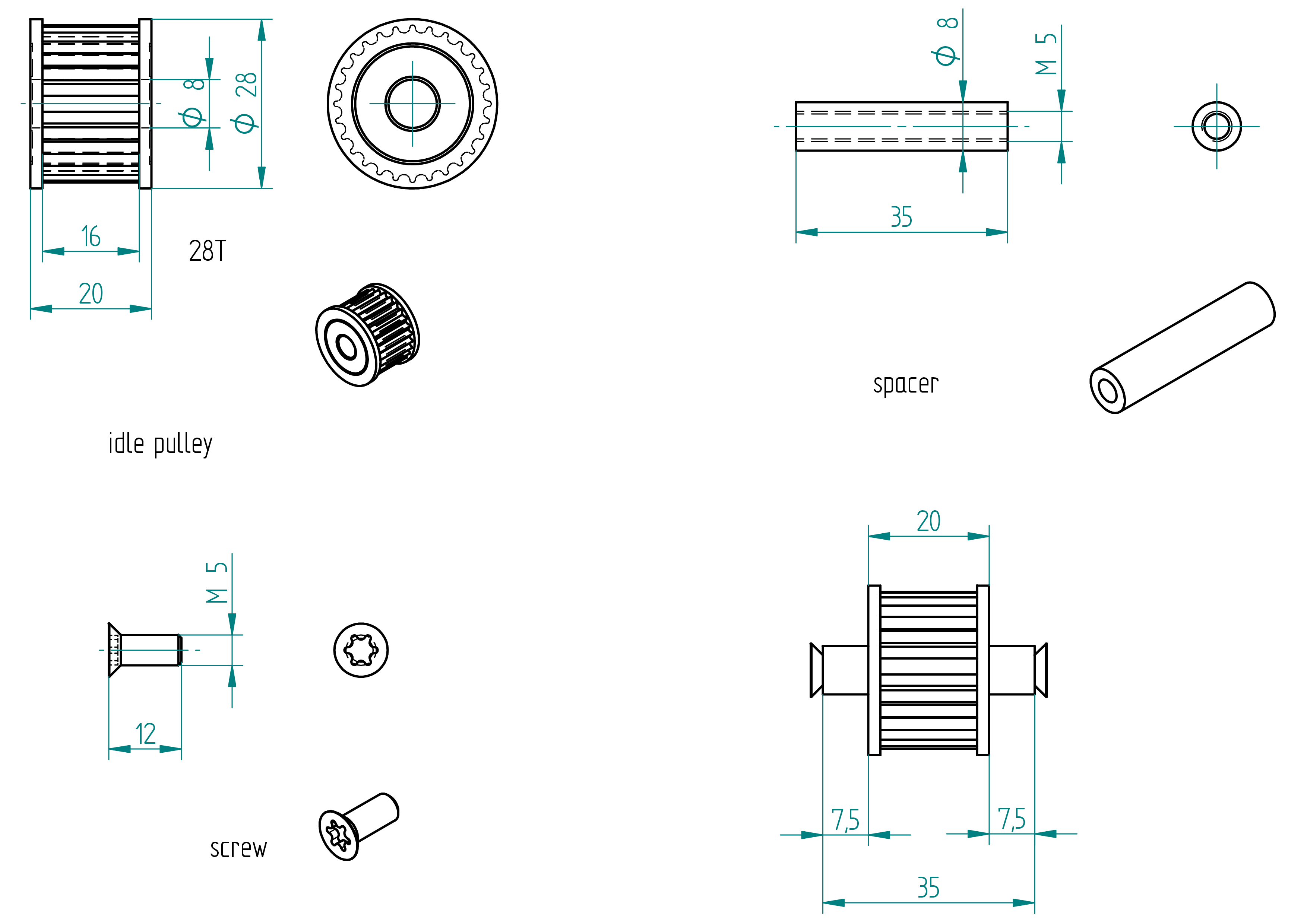
Assembling Instructions
Required Tools and Components
- 1x idle pulley ;
- 1x spacer ;
- 1x depth gauge ;
- 1x shaft glue (Loctite 238) ;
- 1x sandpaper ;
- 1x driller ;
- 1x M5 threader shaft ;
- 1x acetone.
- Test the idle pulley on the spacer. There should be a between them (for the shaft glue).
- If there is no gap :
- Insert the threaded shaft into the spacer and mount it in a drill.
- Use sandpaper to carefully reduce the outer diameter of the spacer until the idle pulley fits with a slight gap.
- Clean the spacer and the idle pulley with acetone.
- Apply shaft glue to the spacer.
- Press the idle pulley onto the spacer, using a depth gauge to ensure correct positioning (see position Drawing).
- Let it cure for 4 hours.
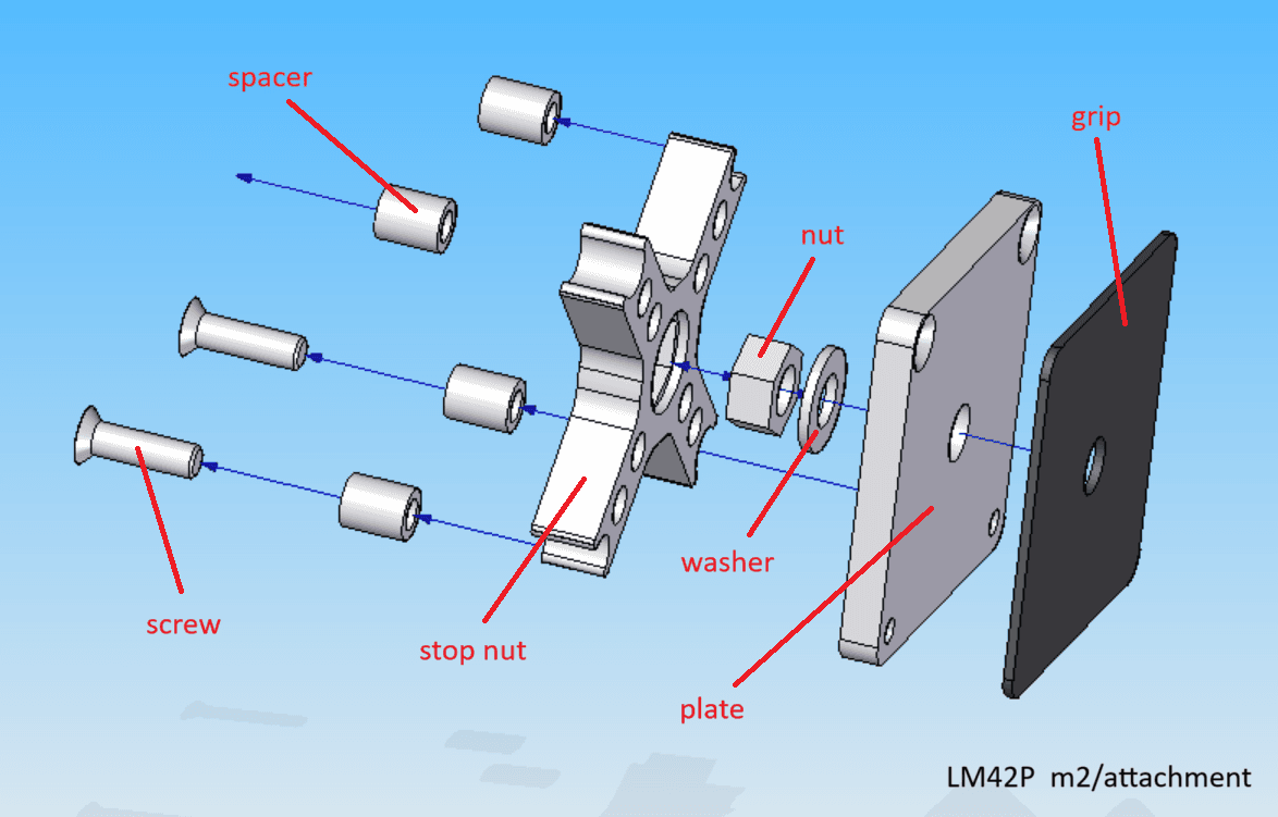
attachment

Parts list
| Qty | Part | Description | Material |
|---|---|---|---|
| 1 | plate | 57 x 57 x 6 | aluminium |
| 1 | stop nut | 3D Printed | PLA |
| 1 | nut | M8 | brass |
| 1 | washer | M8 x 8 x 35 mm | stainless steel |
| 4 | spacer | 8 / 5 × 10 mm | aluminium |
| 2 | screw | M5 x 18 mm Torx flat head screw | stainless steel |
| 1 | grip | 57 x 57 | Griptape (skateboard) |
Drawing
.
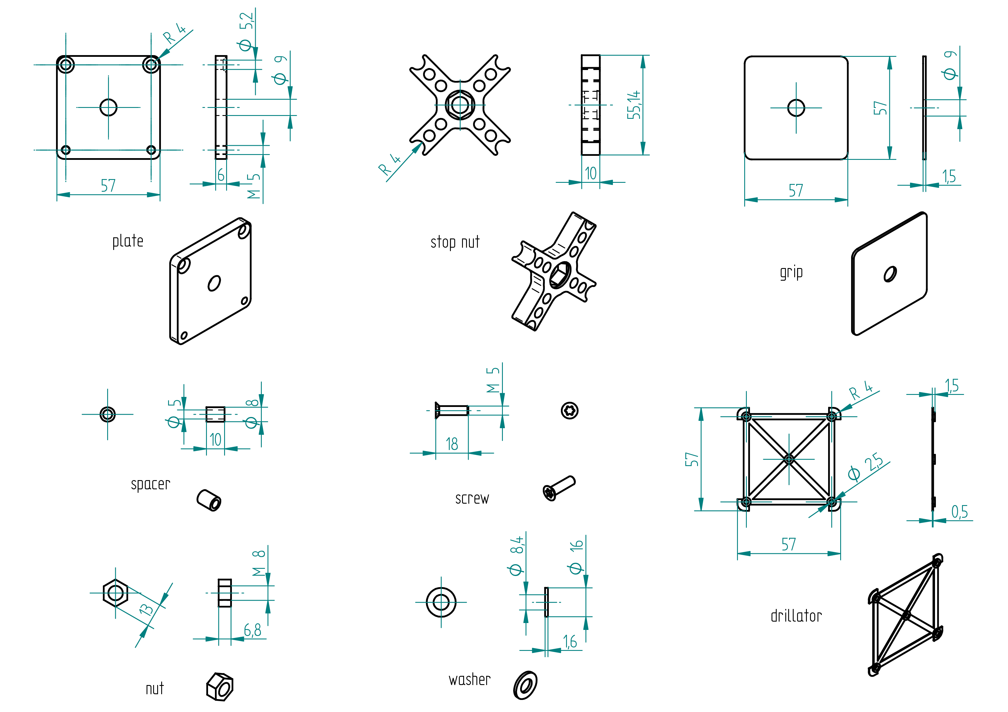
Manufacturing Instructions
Required Tools and Components
- 1x aluminium plate 57 x 57 x 6 mm ;
- 1x 3D printer ;
- 1x PLA ;
- 1x STL file (stop nut) ;
- 1x STL file (drillator) ;
- 2x clamp ;
- 1x scriber ;
- 1x file ;
- 1x 2.5 mm drill bit ;
- 1x 5.2 mm drill bit ;
- 1x 4.2 mm drill bit ;
- 1x 9 mm drill bit ;
- 1x M5 tap ;
- 1x Griptape 57 x 57 mm (use for skate board) ;
- 1x drill press ;
- 1x driller.
- 3D print the drillator ;
- 3D print the stop nut ;
- clamp the drillator on the aluminium plate ;
- scribe the 4x radii and the holes ;
- drill and tap all holes ;
- file the 4 radii ;
- file the sharp edges ;
- cut and drill the grip.
Assembling Instructions
All screws must be glued using threadlock glue.
- Fabricate the shaped tools: the tensionator and the drillator (refer to section tensionator and drillator).
- Rivet the rail onto the housing U-profile.
- Slide the junction block (assembly) onto the rail.
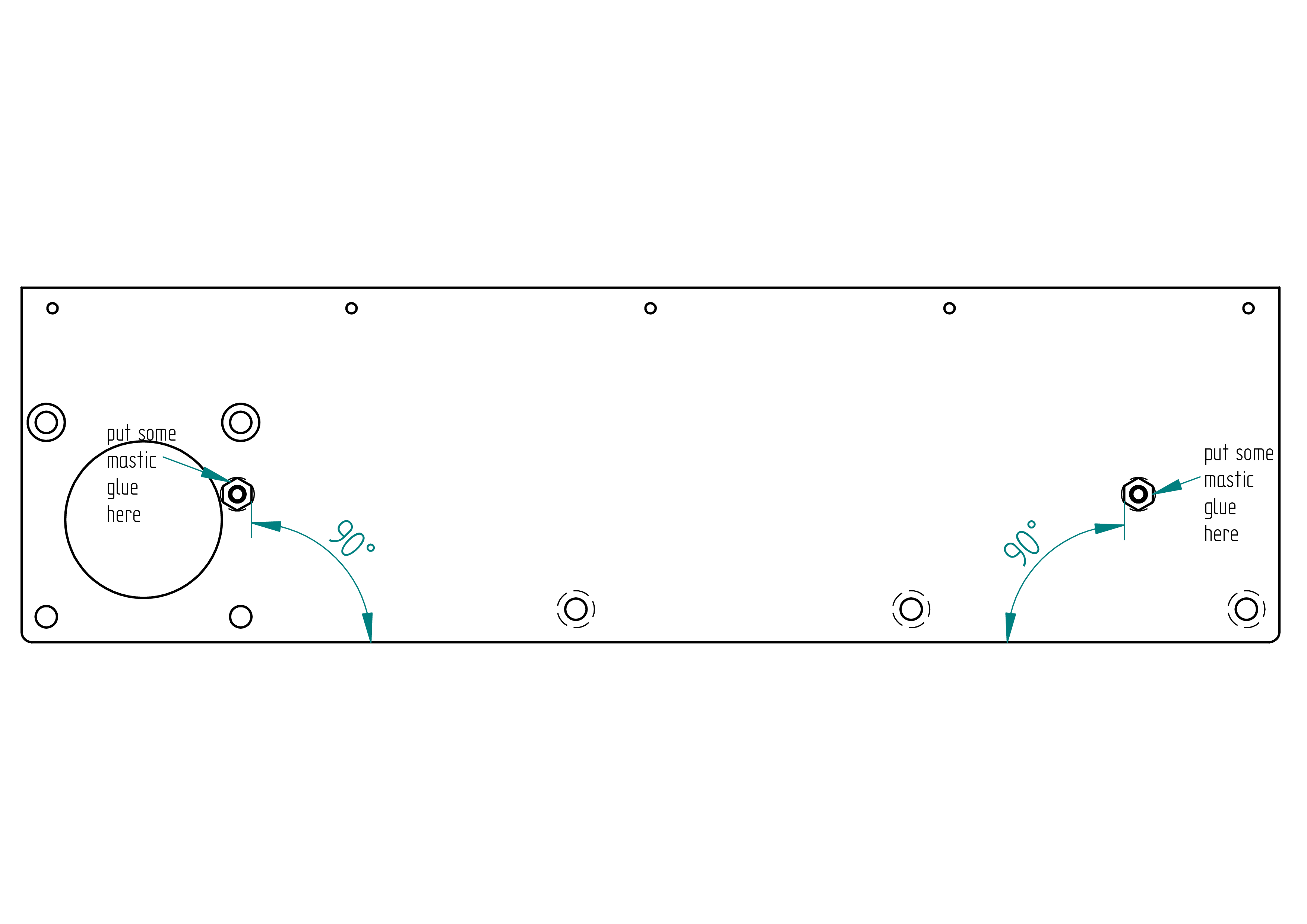
- Mount the stop screw nut, ensuring proper alignment. Glue with threadlock glue and mastic glue. After curing, file the 5x screw so it does not protrude.
- Repeat the previous step to mount the second stop screw nut.
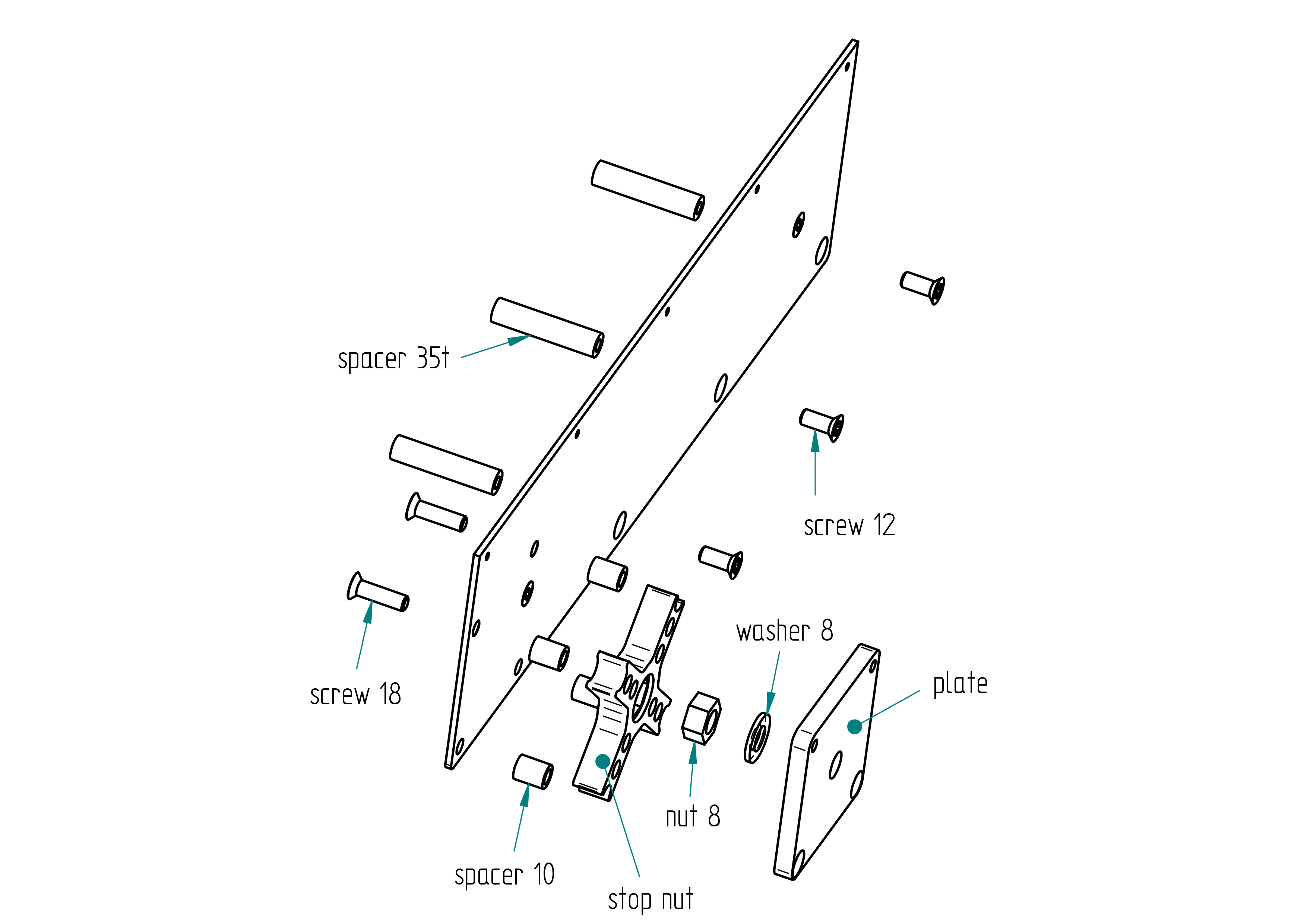
- Assemble the following components:
- 3 × spacer 35
- 3 × screw 12
- 4 × spacer 10
- 2 × screw 18
- 1 × stop nut
- 1 × nut 8
- 1 × washer 8
- 1 × plate
- Rivet the following:
- 5 × rivet 24
- Secure the motor (assembly) with:
- 2 × screw 12
- 2 × washer 5
- 2 × nut 5

- Close the housing using the idle pulley (assembly), with:
- 2 × screw 65
- 2 × spacer 35
- 2 × washer 5
- 2 × nut 5
- 3 × screw 12
- 5 × rivet 24
- 1 × idle pulley (assembly)
- Attach the shaped tool tensionator to the idle pulley using 2 × colson 4.
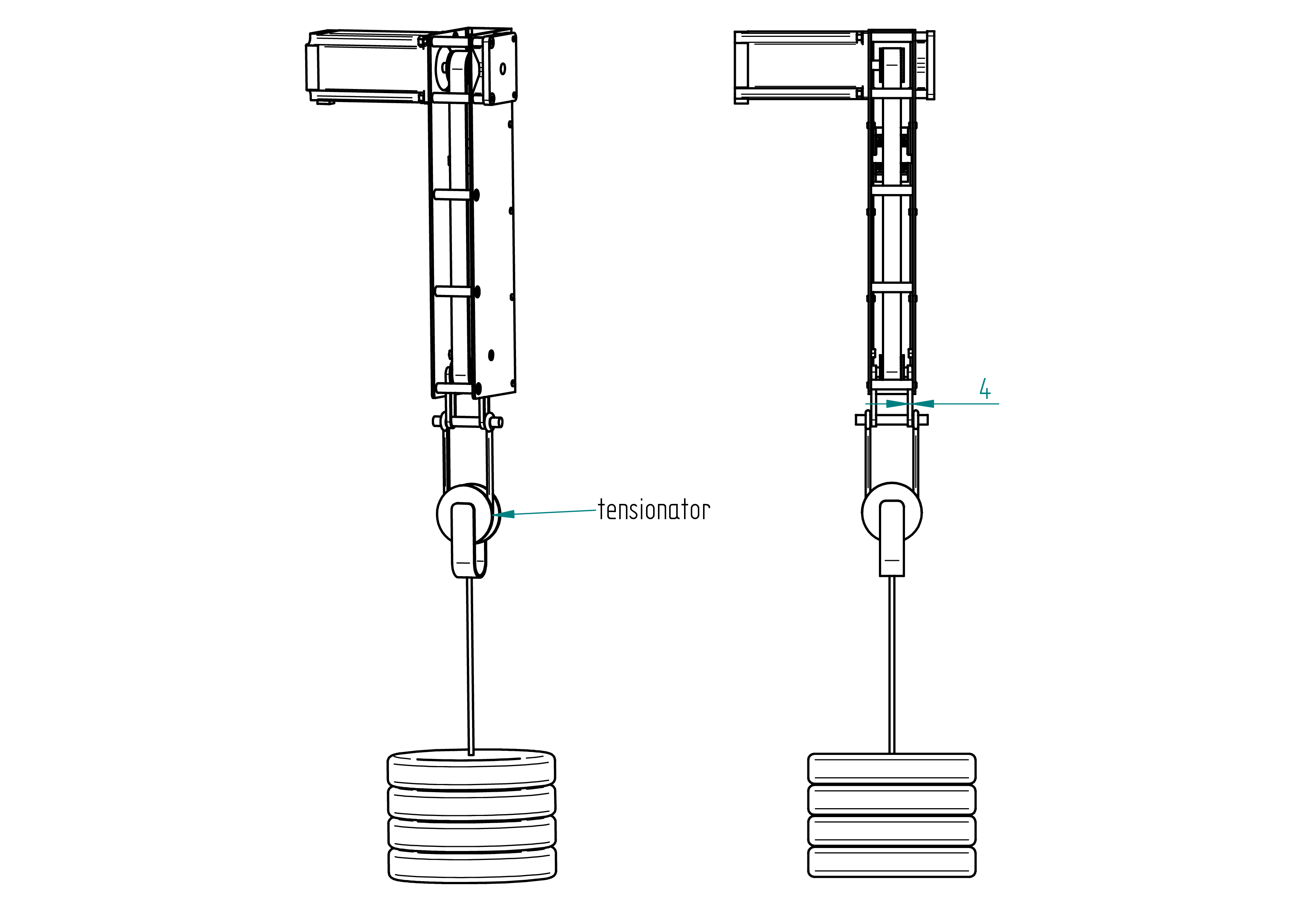
- Place a weight of approximately 17 kg (e.g., 11 × 1.5 L bottles).
- Mount the shaped tool drillator.
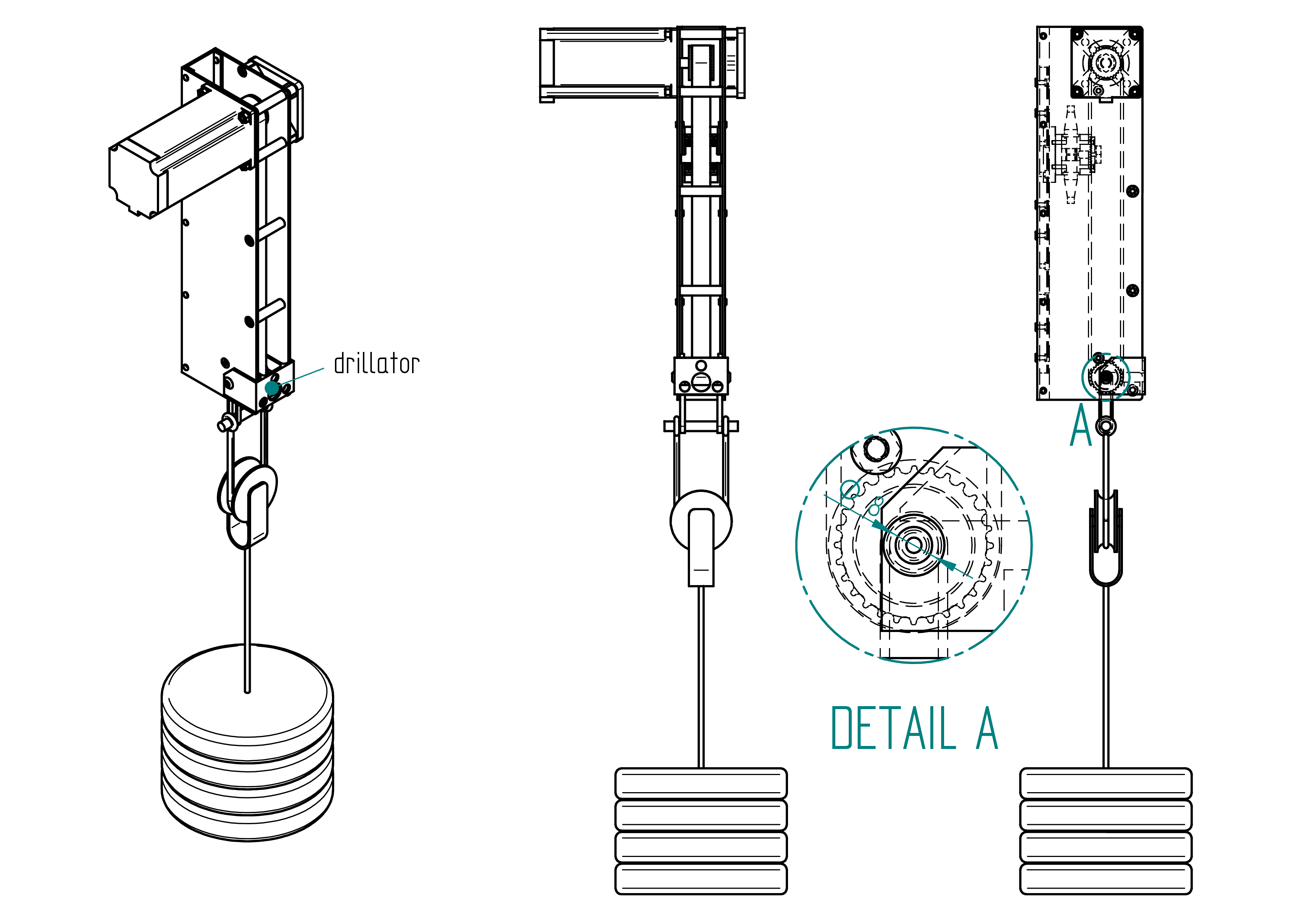
- Mark drill points using a 2.5 mm drill on both sheets.
- Drill with a 5 mm drill, then chamfer the holes.
- Tighten the idle pulley using 2 × screw 12.
- Well Done you've finished the m2 !
drillator
This section shows how to make the shaped tool named drillator The purpose of this tool is to point the holes of the idle pulley shaft during tensioning the belt.
Drawing
The following figure shows the drawing of the drillator.
Details
- Quantity: 1 ;
- Material: PLA ;
Manufacturing Instructions
- 3d print the drillator the files are in the folder named 3d-print-files.
tensionator
This section explains how to build the shaped tool called the tensionator for the assembly of the m2 machine.
The following figure shows the drawing of the tensionator with all its elements.
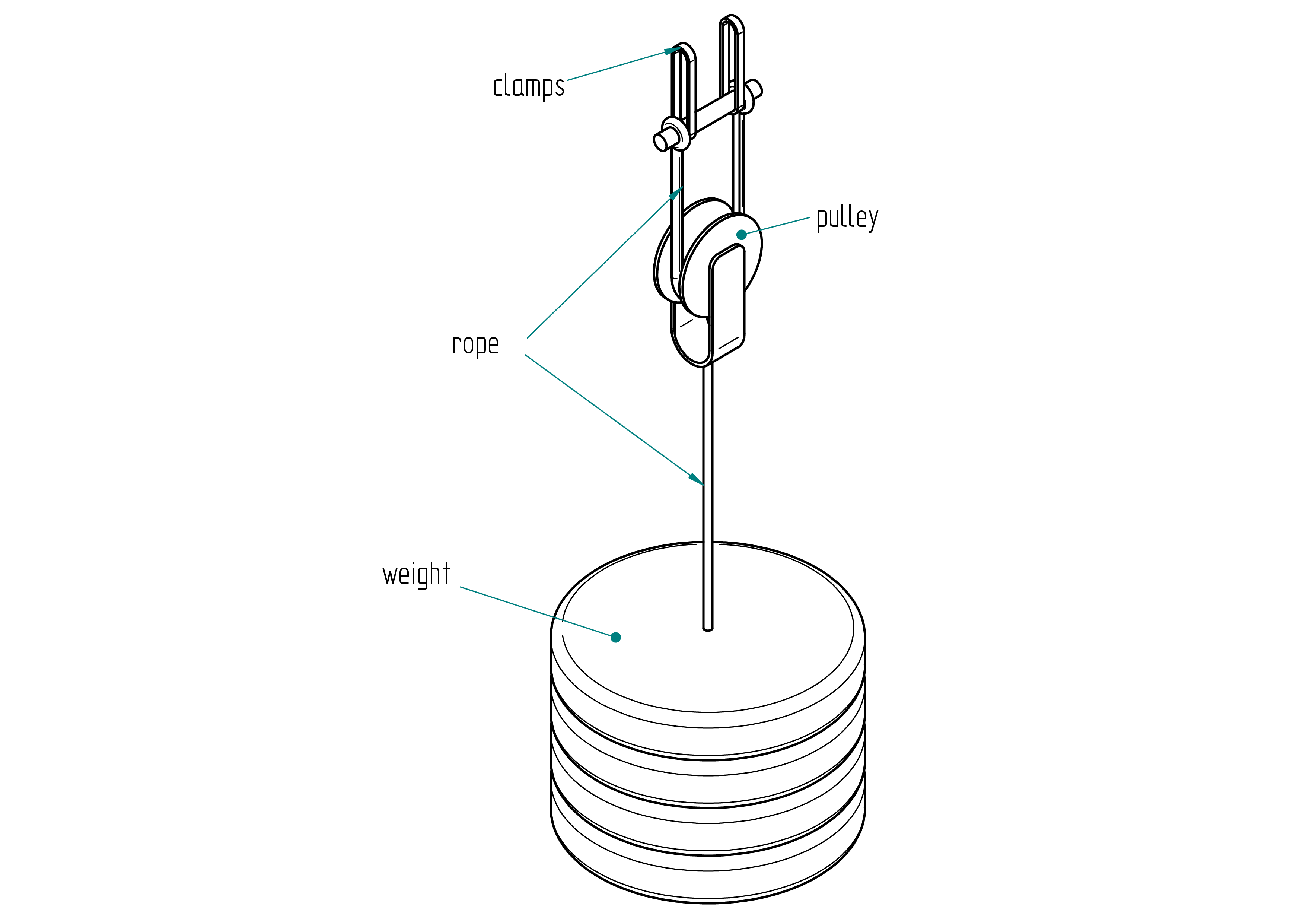
| Qty | Part | Description | Material |
|---|---|---|---|
| 1 | pulley | D50 mm | - |
| 1 | colson | 4 mm | - |
| 2 | rope | - | - |
| 1 | weight | 17 kg | - |
m2 accessories
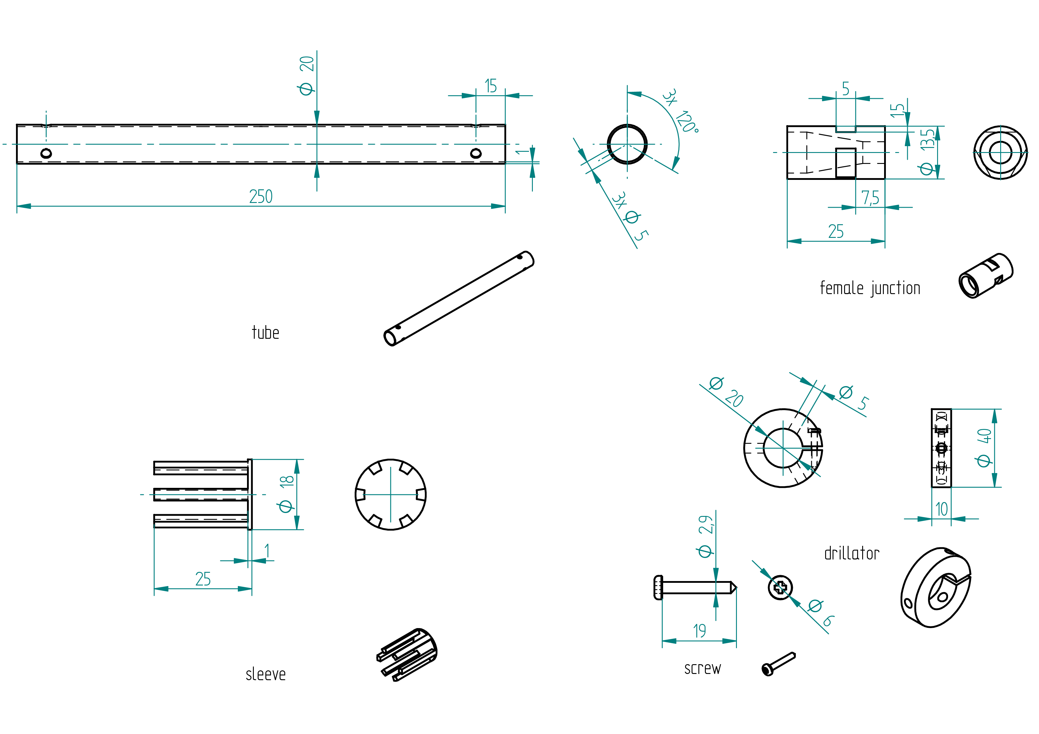
rod
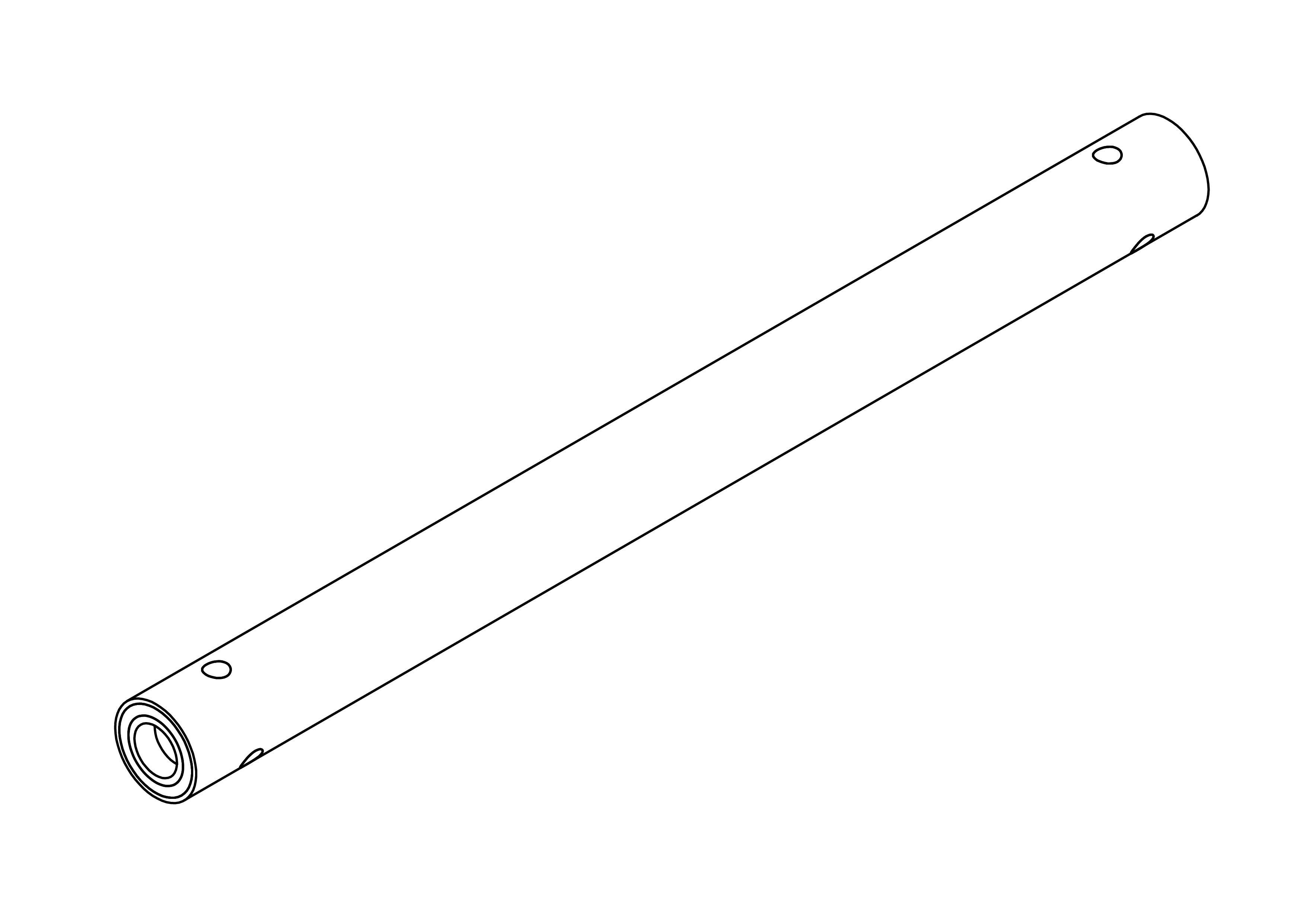
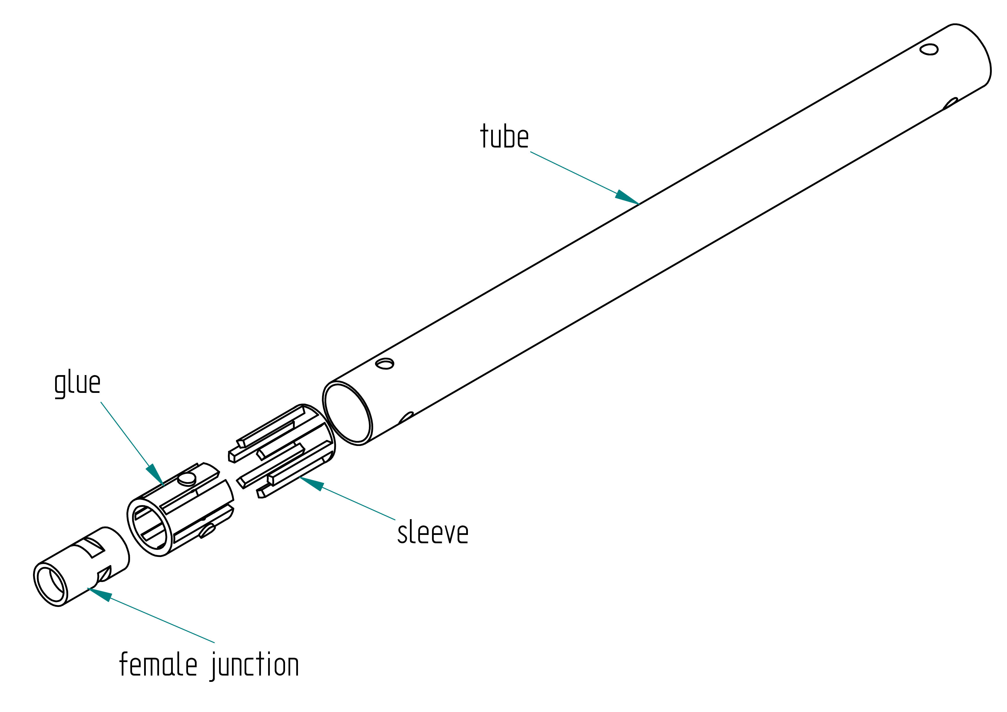
Parts list
| Qty | Part | Description | Material |
|---|---|---|---|
| 1 | tube | 20/18,length: 250 mm | carbon |
| 1 | female junction | google : pool cue junction | brass |
| 1 | sleeve | 3D printed | PLA |
| 1 | glue | resin, hardner, graphite powder |
Drawing
.
Manufacturing Instructions
Required Tools and Components
- 1x carbon tube length: 500 mm ;
- 1x paper ;
- 1x tape ;
- 1x handsaw ;
- 1x perpendiculator ;
- 1x drillator ;
- 1x 5mm drill bit ;
- 1x driller ;
- 1x sandpaper ;
- 1x 3D printer ;
- 1x PLA filament ;
- 2x female junction ;
- 1x file ;
tube
- Scribe a mark at the exact middle of the carbon tube.
- Wrap a piece of paper around the tube and secure it with tape (to guide the cut).
- Use a handsaw to cut the tube into two equal parts.
- Make both ends of each tube perpendicular using the perpendiculator tool.
- Remove the sharp edges with sandpaper.
- Drill the 6 holes using the driller and the drillator tool (refer to the Drawing section).
- Remove the sharp edges again with sandpaper.
sleeve
- 3D print the part using the files located in the
3d-print-filesdirectory. - Chamfer the edges using a file.
- Insert the female junction into the sleeve and gently push it into the tube. Adjust if there is too much friction or too large a gap.
female junction
- File the three 5/1.5mm flats—see dimensions in the Drawing section.
Assembly Instructions
Required Tools and Components
- 1x hot glue ;
- 1x male junction ;
- 1x tape ;
- 1x scale ;
- 1x glue :
- resine:
- Brand: ? ;
- Type: ?.
- hardner:
- Brand: ? ;
- Type: ?.
- resine:
- 1x graphite powder :
- Brand: Suter Kunstoff AG ;
- Type: West Graphit-Pulver 423.
- 1x clamp ;
- 1x piano wire ;
- 1x oven ;
- 1x perpendicalor.
- Screw the male junction into the female junction.
- Seal the hole with hot glue.
- Trim any excess hot glue using a scalpel.
- Unscrew the male junction.
- Thoroughly clean the outside and top of the female junction with acetone.
- Seal the hole with tape.
- Using a scalpel, carefully cut the tape around the female junction.
- Insert the female junction into the sleeve, ensuring the flat side aligns with the canals inside the sleeve.
- Push the assembly into the tube until the female junction is aligned with the end of the tube. Use a ruler for accuracy. Press on the tape — it's normal for the female junction to move slightly inward due to the tape's thickness.
- Wrap tape around the end of the tube, with the tape's edge extending about 1 mm above the end of the tube.
- To glue two female junctions, prepare the following mixture:
- 1.5 g of hardener ;
- 3.75 g of resin ;
- 1.125 g of graphite powder.
- Prepare glue, as described in the shaped-parts section, and mix it with graphite powder.
- Use a clamp to hold the tube vertically.
- Pour the glue mixture above the tape, letting it slightly overflow past the end of the tube.
- Use piano wire to enter each canal of the sleeve, removing any bubbles and ensuring glue flows properly into the canals.
- Let the glue set for 2 hours.
- After 2 hours, check the level of the composite. Add more if necessary.
- Allow to cure for 24 hours, or place in an oven to accelerate curing.
- Use the perpendiculator to grind the end of the tube until the tape sealing the female junction is removed (you should see a shiny ring appear).
- Repeat the same steps for the other end of the tube.
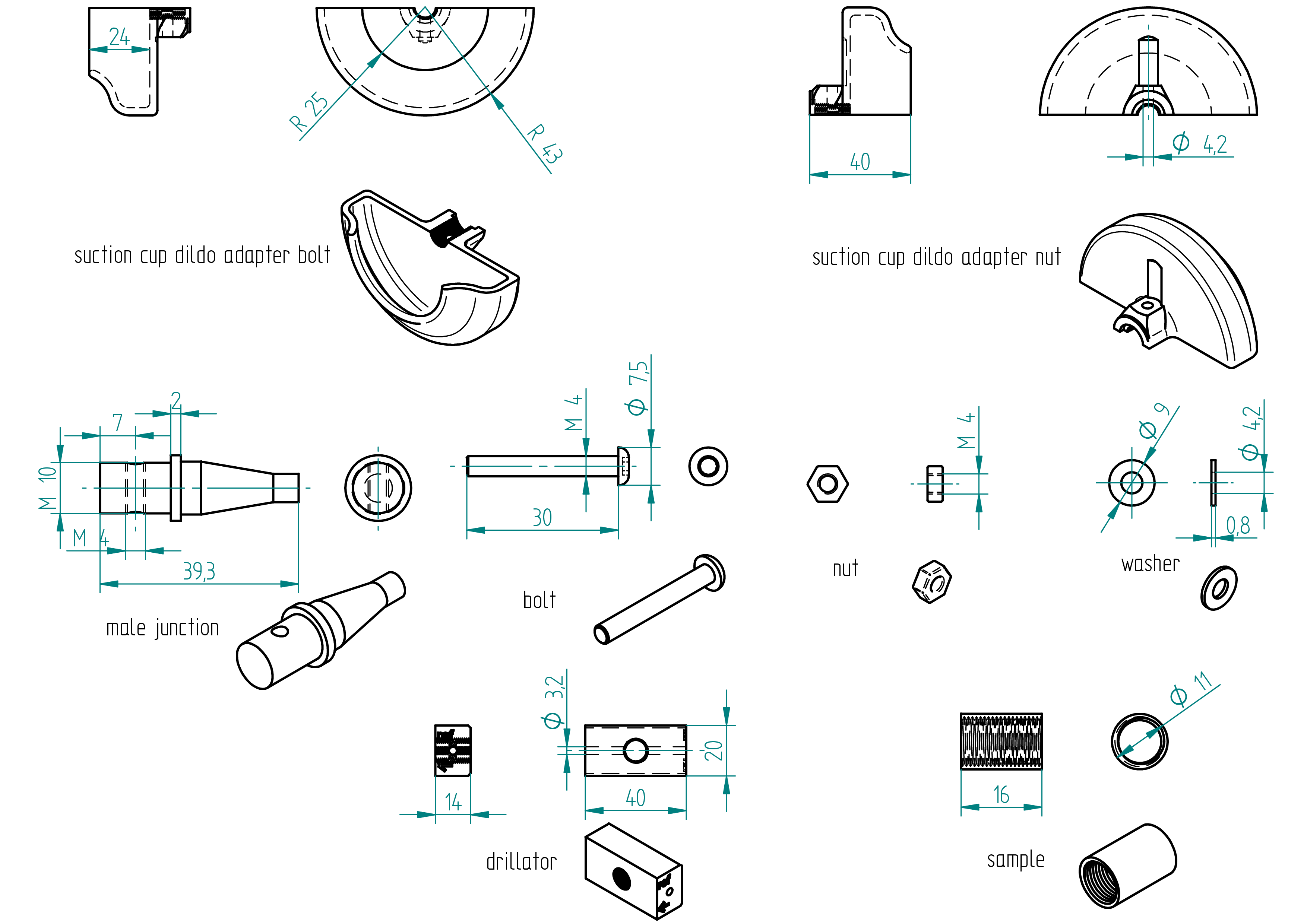
suction cup dildo adapter
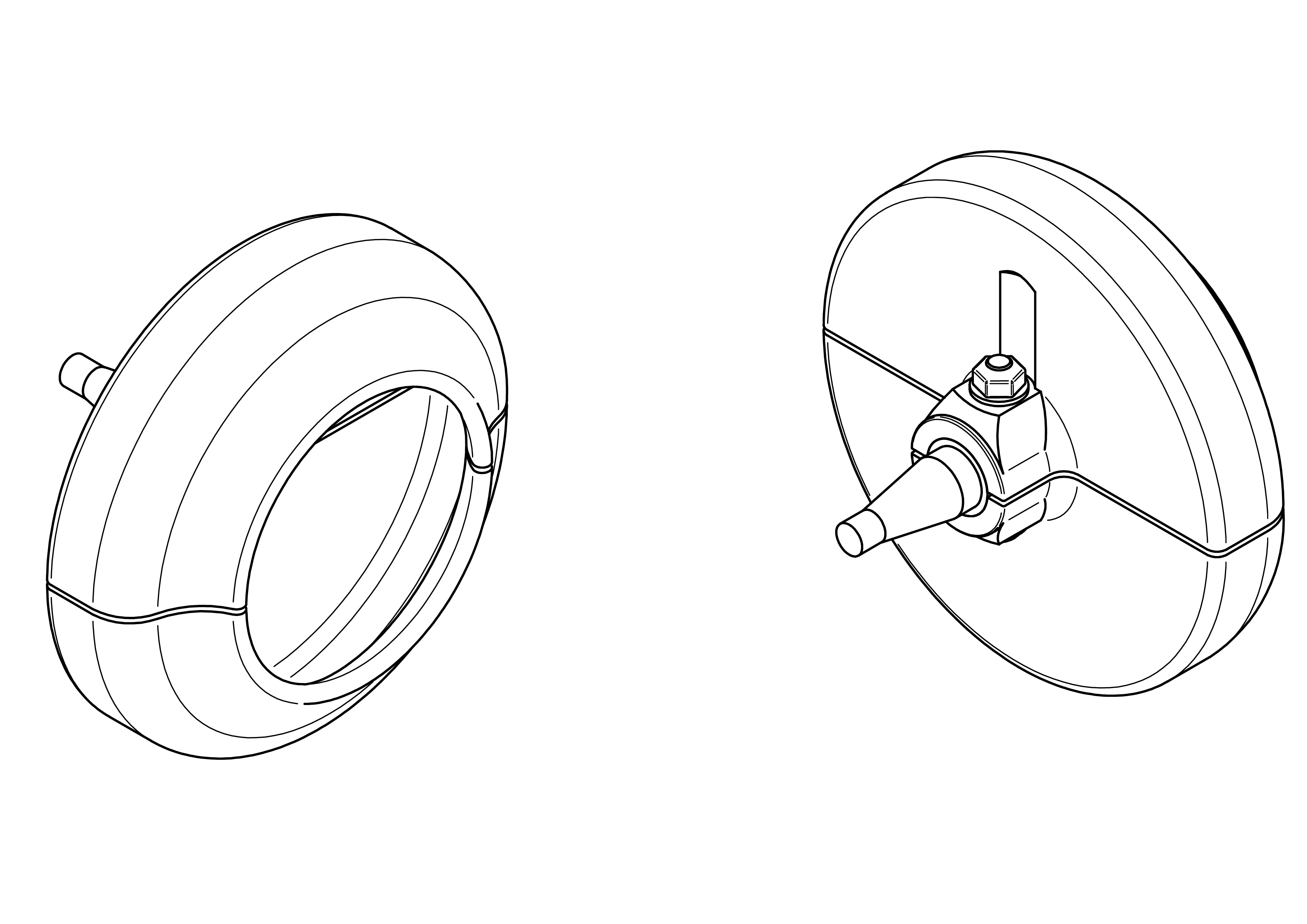
This section explain how to build the suction cup dildo adapter for the m2 machine.
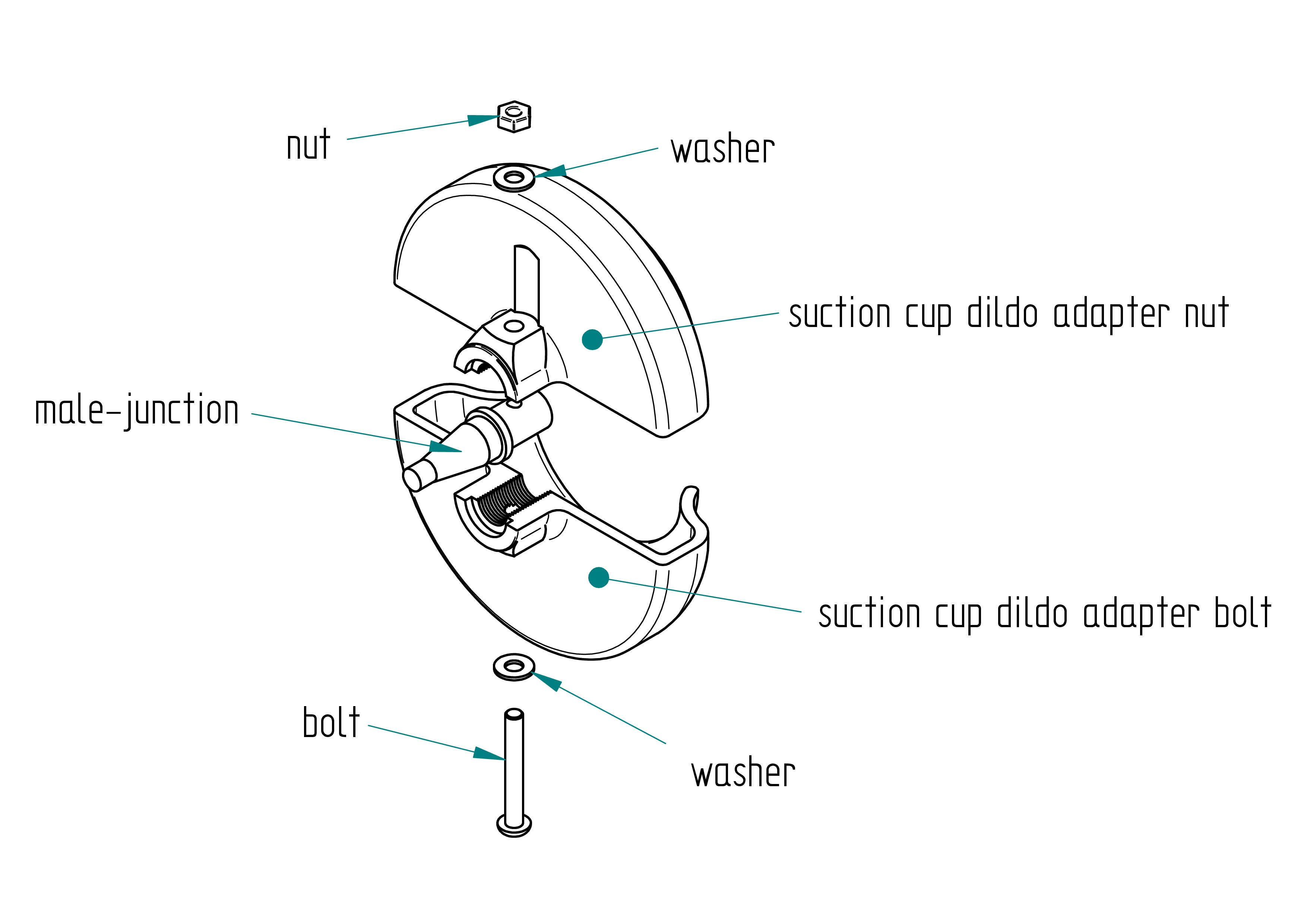
Parts list
| Qty | Part | Description | Material |
|---|---|---|---|
| 1 | suction cup dildo adapter nut | 3D printed | PLA |
| 1 | suction cup dildo adapter bolt | 3D printed | PLA |
| 1 | male junction | google : pool cue junction | brass |
| 1 | bolt | M4 x 30 mm | stainless steel |
| 1 | nut | M4 | brass |
| 2 | washer | M4 | stainless steel |
Drawing
.
Required Tools and Components
- 1x 3D printer ;
- 1x CAD software (to ajuste M10 tap in case) ;
- 1x PLA ;
- 1x STL file suction cup dildo adapter nut ;
- 1x STL file suction cup dildo adapter bolt ;
- 1x STL file drillator ;
- 1x STL file sample ;
- 1x male junction ;
- 1x bolt ;
- 2x washer ;
- 1x nut ;
- 1x file ;
- 1x 3.2 mm drill bit ;
- 1x chamfer mill ;
- 1x M4 tap ;
- 1x tap wrench ;
- 1x boltdriver ;
- 1x drill press ;
- 1x driller ;
- 1x water pump pliers ;
- 1x allen key ;
- 1x threaderlock glue ;
- 1x bench vise.
Manufacturing Instructions
- Skip the next three steps if all 3D printers used print with the same accuracy as an Ultimaker.
- 3D print the sample.
- Test if the M10 tap fits into the sample.
- Adjust the M10 tap size on the suction cup dildo adapter nut, suction cup dildo adapter bolt, and drillator 3D models as needed.
- Remark : Before printing the suction cup dildo adapter nut and the suction cup dildo adapter bolt, adjust the starting position of the M4 thread. The drillator was originally designed for a 2mm male junction, but since the actual male junction is located at 0.5 mm, I had to shift the thread start by 0.5 mm to compensate. the male juction was not at 2mm but at 2.5mm. 3D print the suction cup dildo adapter nut, suction cup dildo adapter bolt, and drillator.
- Screw the male junction into the drillator (the large diameter with a width of 2 mm should be flush against the reference plane). Use water pump pliers.
- On a drill press, drill a 3.2 mm hole.
- File or chamfer the hole.
- Tap an M4 thread.
- Assemble the male junction and suction cup dildo adapter bolt with the bolt. Don’t forget to apply thread locker.
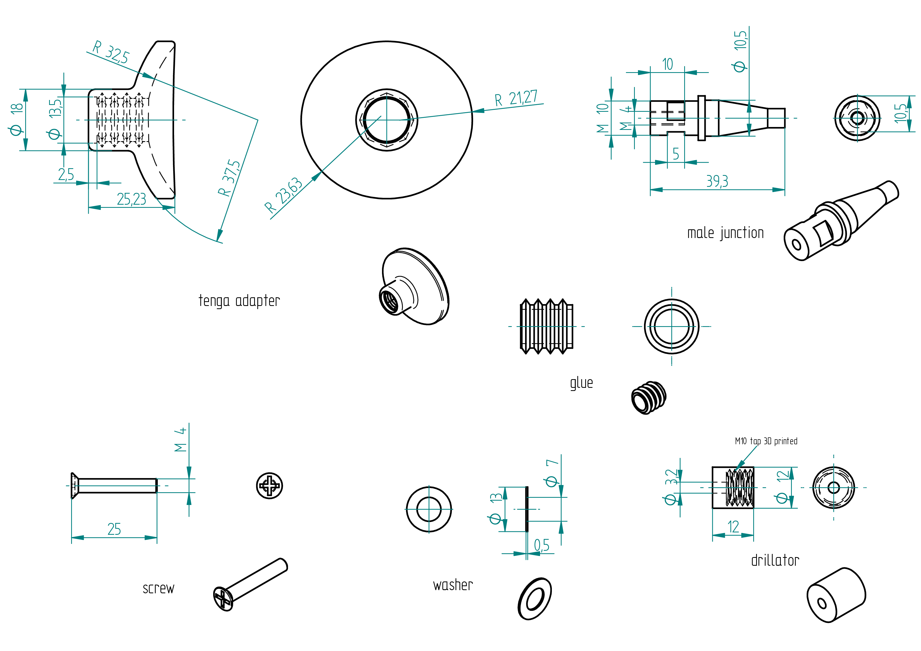
tenga adapter
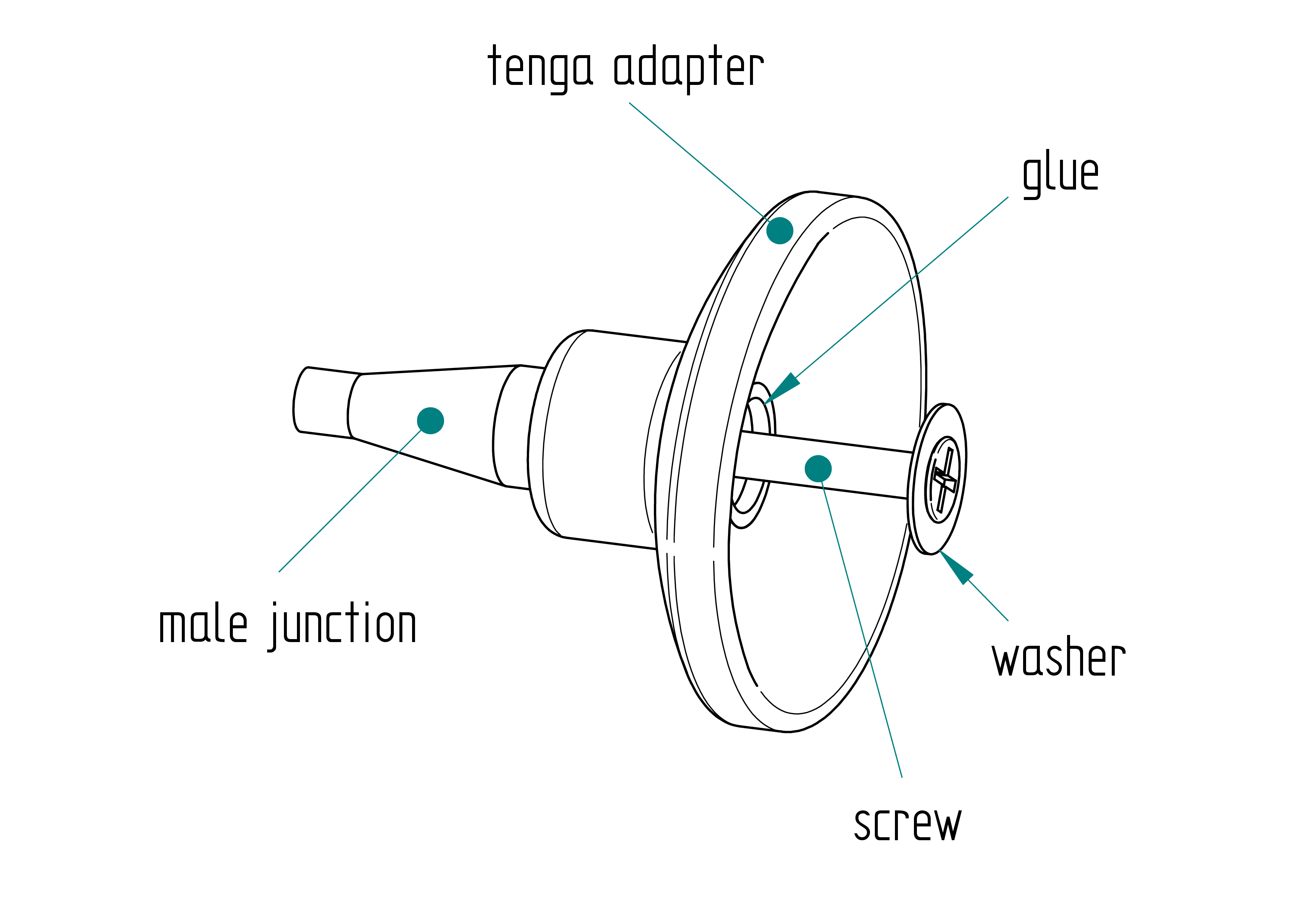
Parts list
| Qty | Part | Description | Material |
|---|---|---|---|
| 1 | tenga adapter | 3D Printed | PLA |
| 1 | male junction | M10 x 39.3 mm | PLA |
| 1 | glue | casted | epoxy and grafite powder |
| 2 | screw | M4 x 25 mm Torx flat head screw | stainless |
| 1 | washer | M7 x 13 x 0.5 mm | stainless steel |
| 1 | drillator | 3D Printed | PLA |
Drawing
.
Required Tools and Components
- 1x 3D printer ;
- 1x PLA ;
- 1x STL file (tenga adapter) ;
- 1x STL file (drillator) ;
- 1x male junction ;
- 1x female junction ;
- 1x screwdriver ;
- 1x 3.2 mm drill bit ;
- 1x 4.2 mm drill bit ;
- 1x chamfer cutter ;
- 1x M4 tap ;
- 1x left-hand tap ;
- 1x drill press ;
- 1x driller ;
- 1x file ;
- 1x tape ;
- 1x cutter ;
- 1.5 g of hardener ;
- 3.75 g of resin ;
- 1.125 g of grafite powder ;
- 1x wood chisel.
Manufacturing Instructions
See also video :
- 3D print the drillator.
- 3D print the Tenga adapter.
- Drill a 4.2 mm hole in the Tenga Fleshlite.
- Insert the male junction into the female junction.
- Using a drill press, drill a 3.2 mm hole.
- Tap an M4 thread into the hole.
- File three flat surfaces on the M10 thread.
- Wrap tape around the M4 thread.
- Trim the tape using a cutter.
- Insert the male junction into the Tenga adapter.
- Prepare the glue mixture:
- 1.5 g of hardener;
- 3.75 g of resin;
- 1.125 g of graphite powder.
- Pour the glue into the assembly.
- Remove any excess glue from the top of the male junction.
- Assemble the Tenga Fleshlite using the screw.
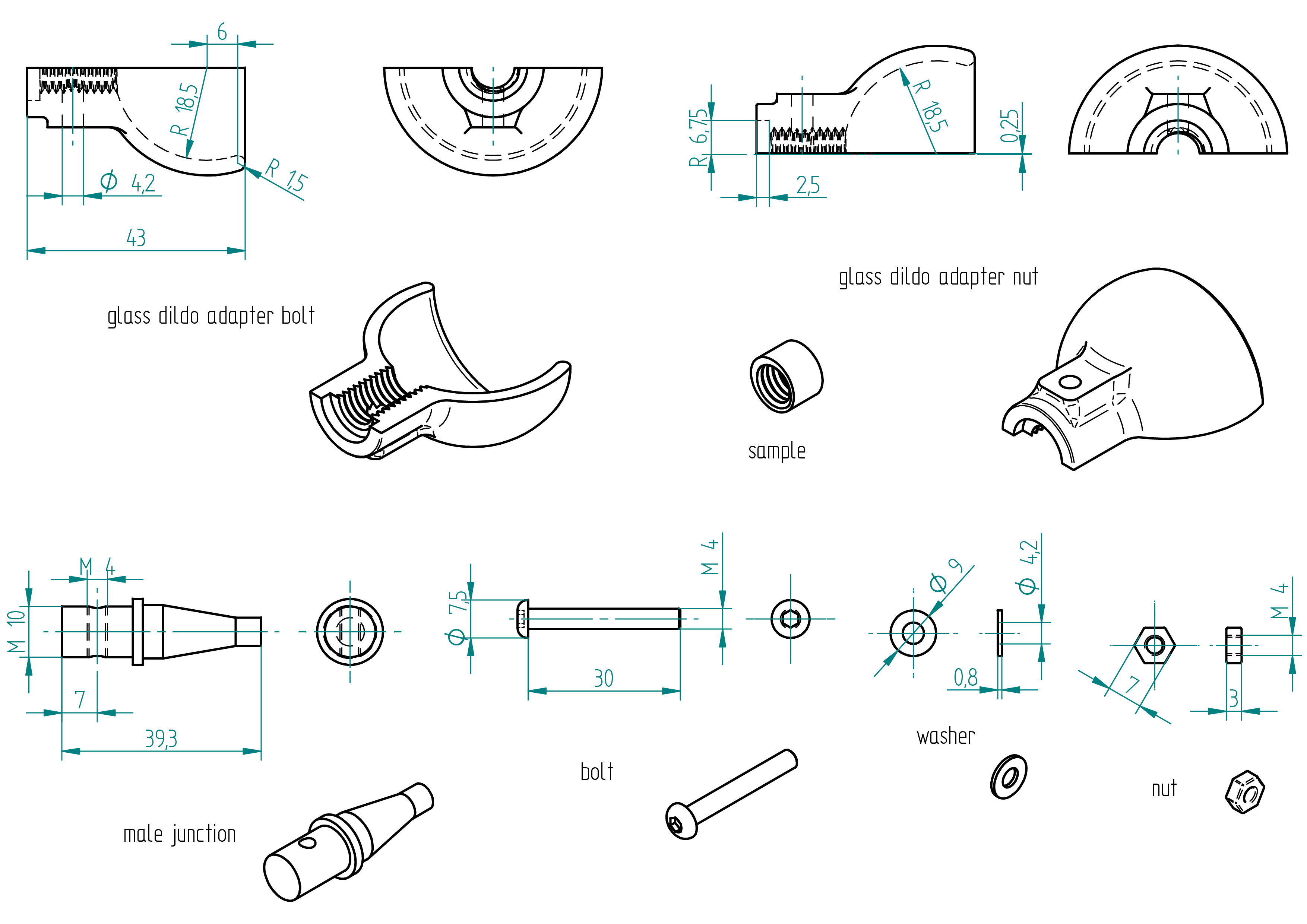
glass dildo adapter
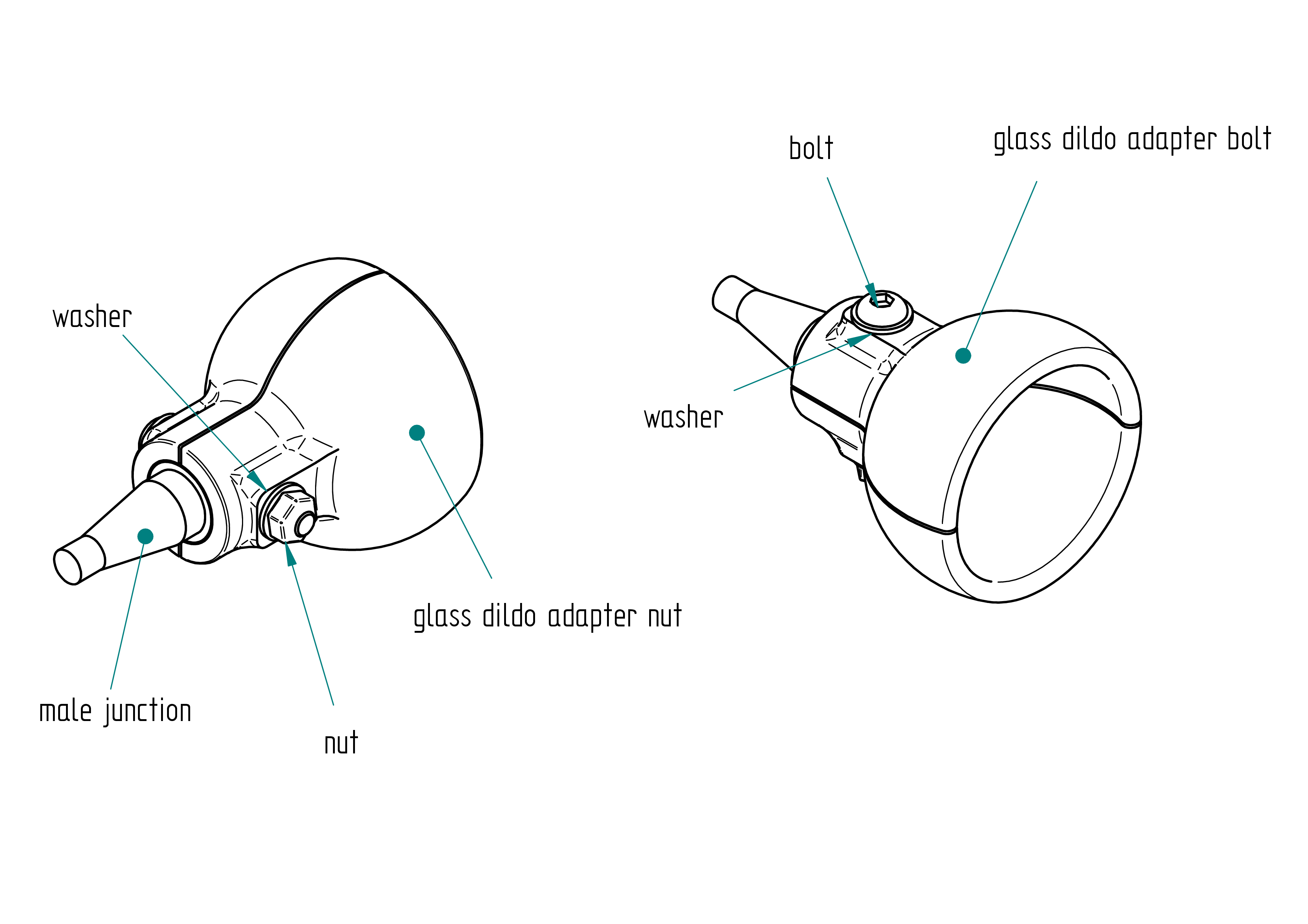
Parts list
| Qty | Part | Description | Material |
|---|---|---|---|
| 1 | glass dildo adapter bolt | 3D Printed | PLA |
| 1 | glass dildo adapter nut | 3D Printed | PLA |
| 1 | male junction | M10 x 39.3 mm | PLA |
| 1 | bolt | M4 x 30 mm Torx flat head screw | stainless steel |
| 2 | washer | M4 x 9 x 0.8 mm | stainless steel |
| 1 | nut | M4 x 3 mm | stainless steel |
Drawing
.
Remark : The position of 6 was previously at 4 mm, and a gap of 0.25 mm has been added. All 3D print files have already been updated accordingly, so the parts are ready for printing with these modifications.
Required Tools and Components
- 1x 3D printer ;
- 1x PLA ;
- 1x STL file (glass dildo adapter) which include both bolt and nut sides ;
- 1x STL file (sample) ;
- 1x STL file (drillator) ;
- 1x male junction ;
- 1x screwdriver ;
- 1x 3.2 mm drill bit ;
- 1x M4 tap ;
- 1x M10 tap ;
- 1x left-hand tap ;
- 1x drill press ;
- 1x driller ;
- 1x file ;
- 1x clamp ;
- 1 x 7 mm open-end wrench ;
- 1x 0.5 mm of sheet ;
- 1x threadlocker (light one).
Manufacturing Instructions
See also video :
- 3D print the sample and check if the M10 tap of the male junction fits snugly into the sample without any gap.
- Adjust the M10 tap on the drillator model.
- 3D print the drillator.
- Adjust the M10 tap on the glass dildo adapter model (both nut and bolt sides).
- 3D print the glass dildo adapter.
- Place a 0.5 mm sheet between the glass dildo adapter parts.
- Clamp all components together.
- Tap the M10 thread.
- Screw the male junction into the drillator.
- Using a drill press, drill a 3.2 mm hole from both sides.
- Tap an M4 thread into the hole.
- File the sharp edges of the M10 thread.
- Insert the male junction into the glass dildo adapter bolt.
- Apply threadlocker to the bolt, add the washer, and tighten everything.
- Assemble the glass dildo adapter nut with a washer and a nut.
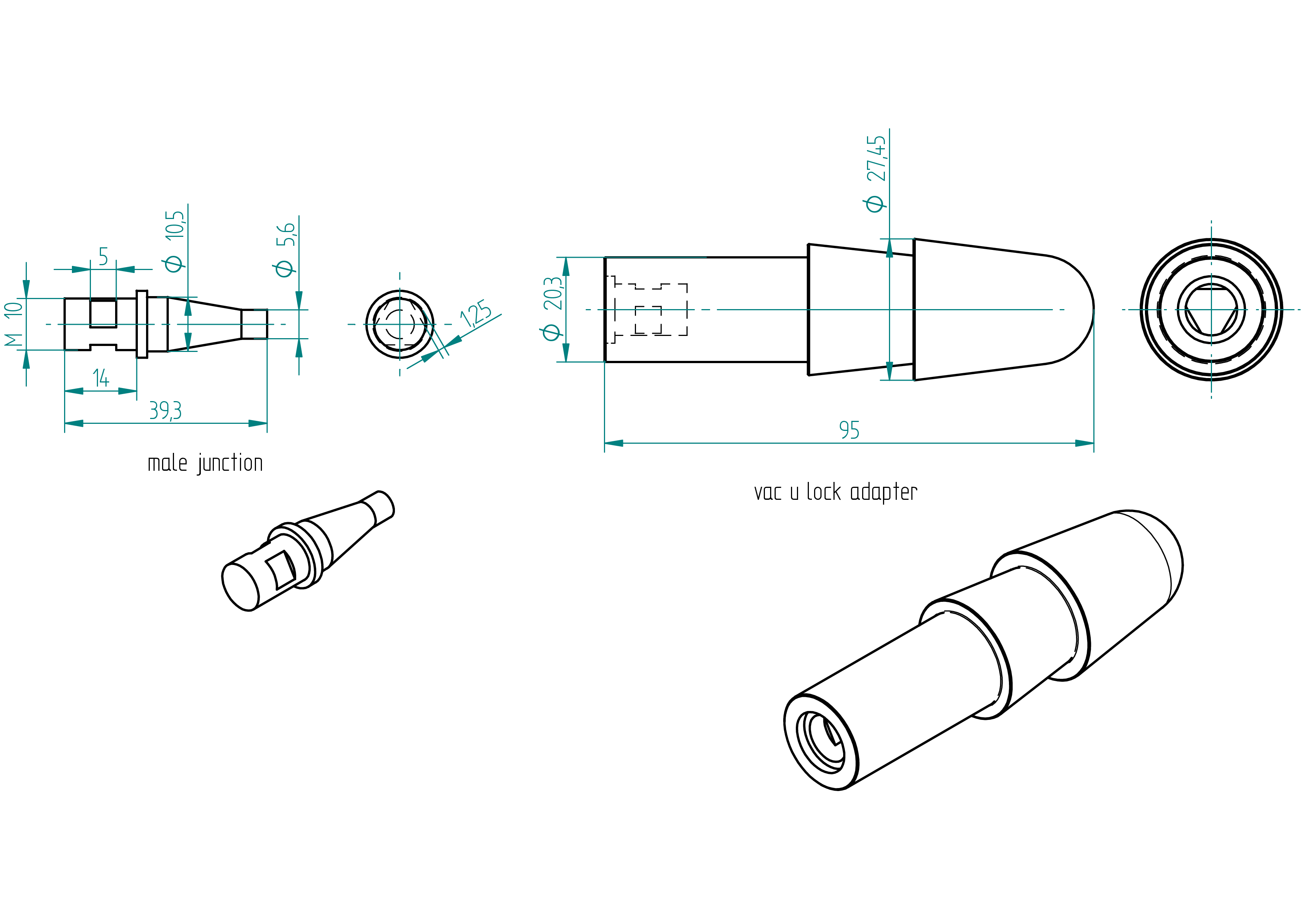
vac u lock adapter
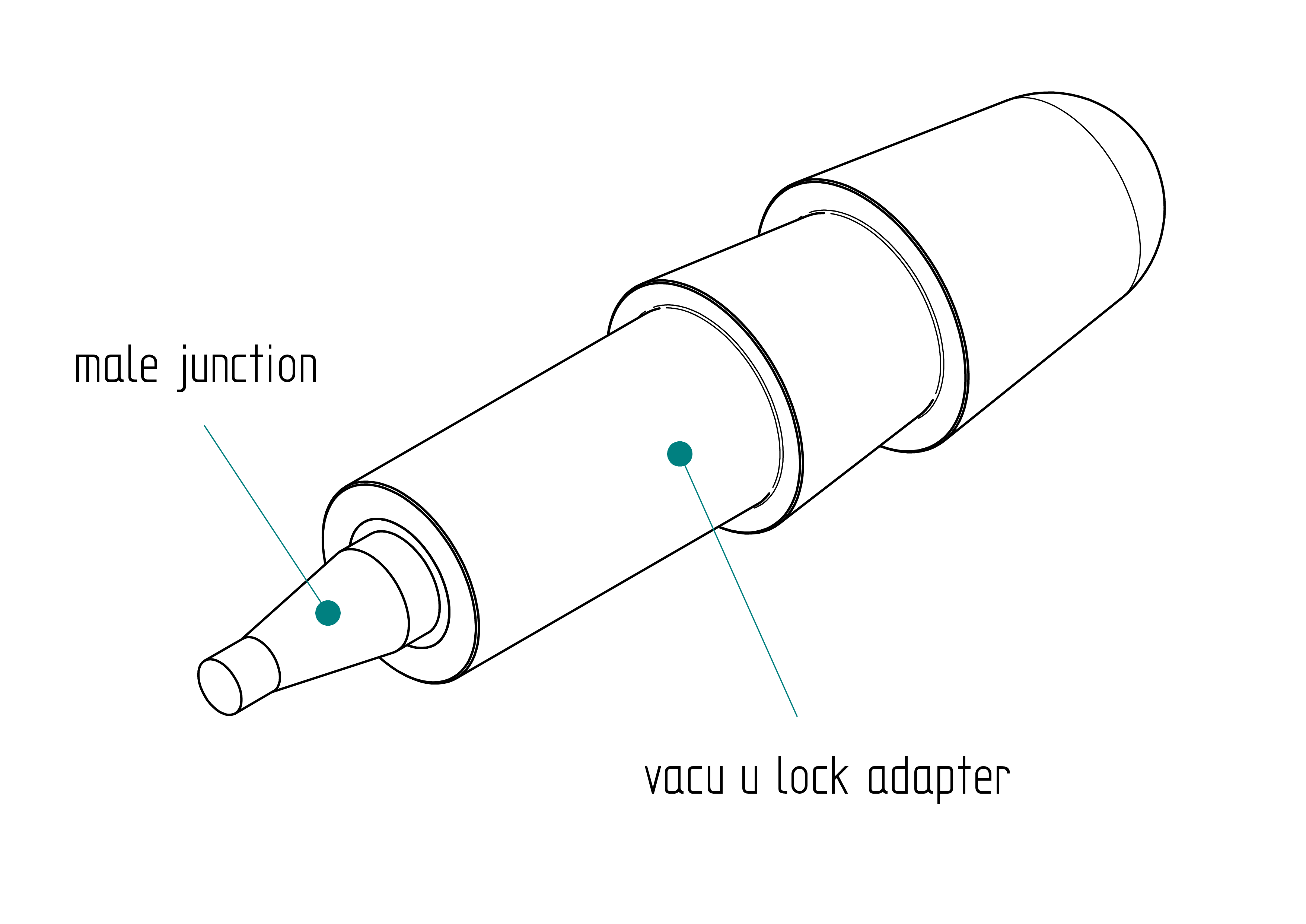
Parts list
| Qty | Part | Description | Material |
|---|---|---|---|
| 1 | vac u lock adapter | molded | composite |
| 1 | male junction | M10 x 39.3 mm | brass |
Drawing
.
Required Tools and Components
- 1x 3D printer ;
- 1x PLA ;
- 1x STL file (mold) ;
- 1x STL file (cover) ;
- 1x male junction ;
- 1x file ;
- ? g of hardener ;
- ? g of resin ;
- ? g of grafite powder ;
- 1x scale ;
- 1x release agent ;
- 1x 1s lipo battery or one AA battery ;
- 1x wooden chisel.
Manufacturing Instructions
See also video : not yet done
- Get the moldator ready (see Section ).
- 3D print the mold.
- Preheat the oven to 40,°C.
- Apply release agent inside the mold.
- Wait 30 minutes.
- Prepare the composite mixture:
- ?,g hardener;
- ?,g resin;
- ?,g graphite powder.
- Insert the male junction into the cover.
- Pour the composite into the mold.
- Gently close the mold with the cover.
- Clamp the mold onto the moldator.
- Connect the battery to the motor.
- Place everything inside the oven.
- Cure for 4 hours.
- Use a wooden chisel to open the mold.
moldator
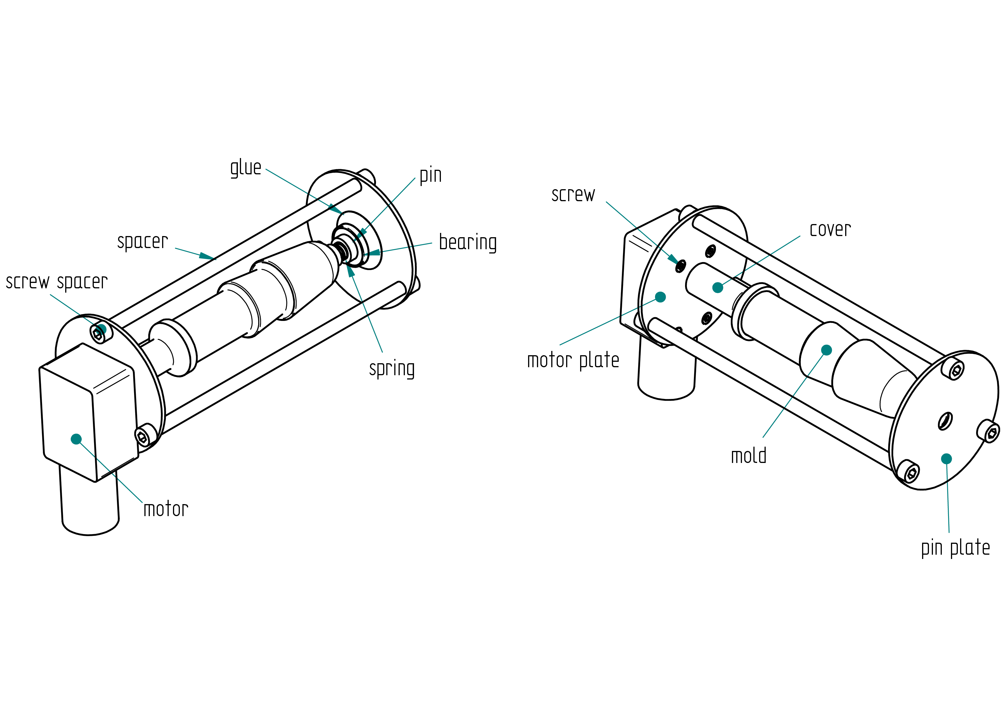
Parts list
| Qty | Part | Description | Material |
|---|---|---|---|
| 1 | motor | standard (worm gear) | - |
| 1 | motor plate | 64 x 2 mm | aluminium |
| 1 | pin plate | 64 x 2 mm | aluminium |
| 3 | spacer | 6 x 4 x 149.15 mm | aluminium |
| 6 | screw spacer | M5 x 12 mm | stainless steel |
| 3 | screw | M3 x 8 mm | stainless steel |
| 1 | mold | 3D printed | PLA |
| 1 | cover | 3D printed | PLA |
| 1 | drillator | 3D printed | PLA |
Drawing
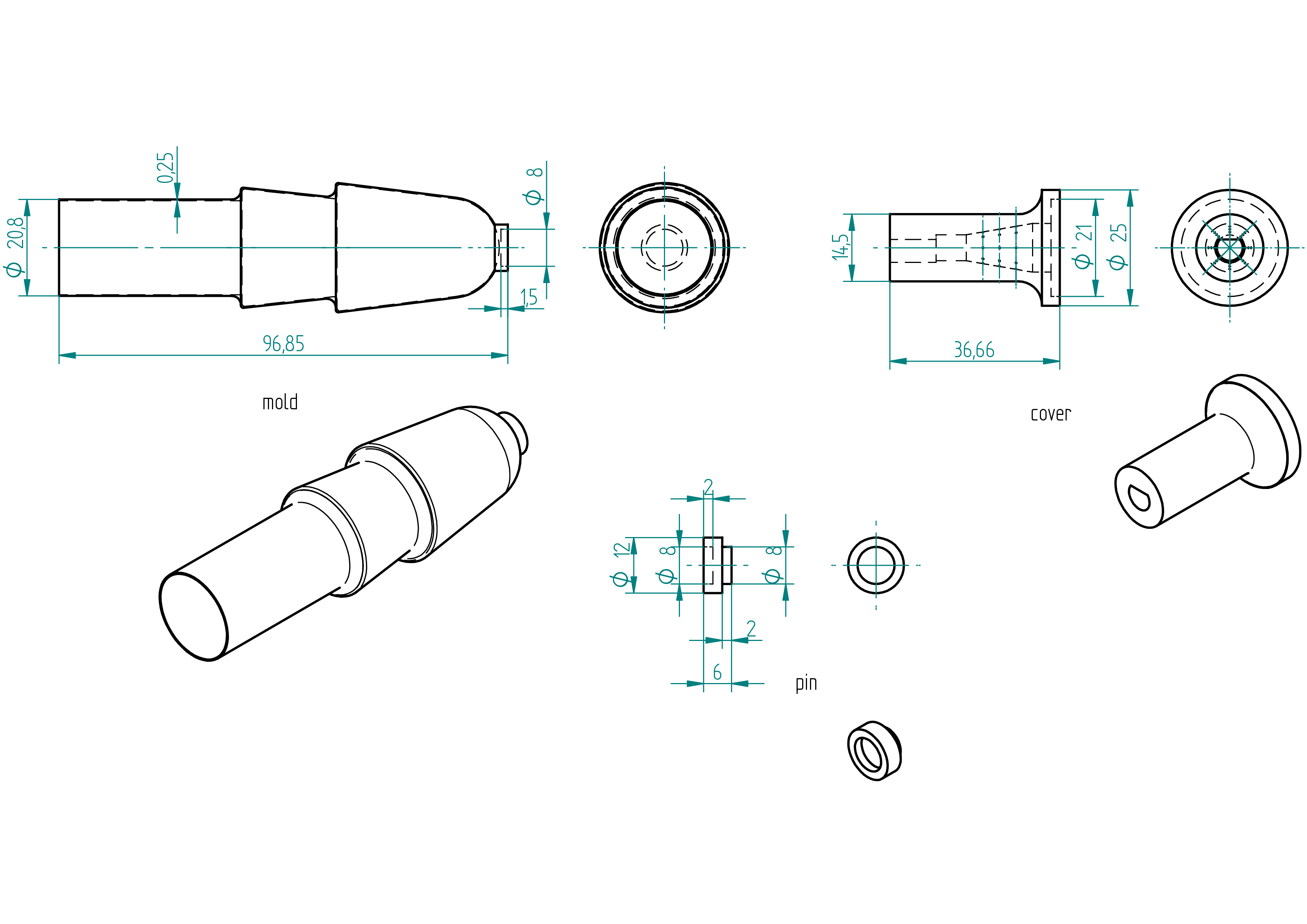
Required Tools and Components
- 1× 3D printer ;
- 1× PLA spool ;
- 1× STL file (drillator) ;
- 1× 2,mm aluminium sheet ;
- 1× screwdriver ;
- 2× clamps ;
- 1× Allen key ;
- 1× 2,mm drill bit ;
- 1× 4.2,mm drill bit ;
- 1× 5.2,mm drill bit ;
- 1× chamfer cutter ;
- 1× M5 tap ;
- 1× left-hand tap ;
- 1× drill press ;
- 1× driller ;
- 1× file ;
- 1× scriber ;
- 1x jigsaw ;
- 1× 8×6,mm aluminium tube (min length 460,mm) ;
- 1× gauge ;
- 1× handsaw ;
- 1× perpendiculator.
Manufacturing Instructions
See also video :
- 3D print the drillator.
- 3D print the cover.
- Clamp the drillator on the 2 mm aluminium sheet at a corner.
- Point with a 2 mm drill bit.
- Scribe the cercle around the drillator.
- Drill all holes (see the drawing).
- Saw with a jig saw the ouside cirle.
- Repeat the five precedent points for the other plate.
- Shape the spacer.
- Assemble every thing like on the figure.
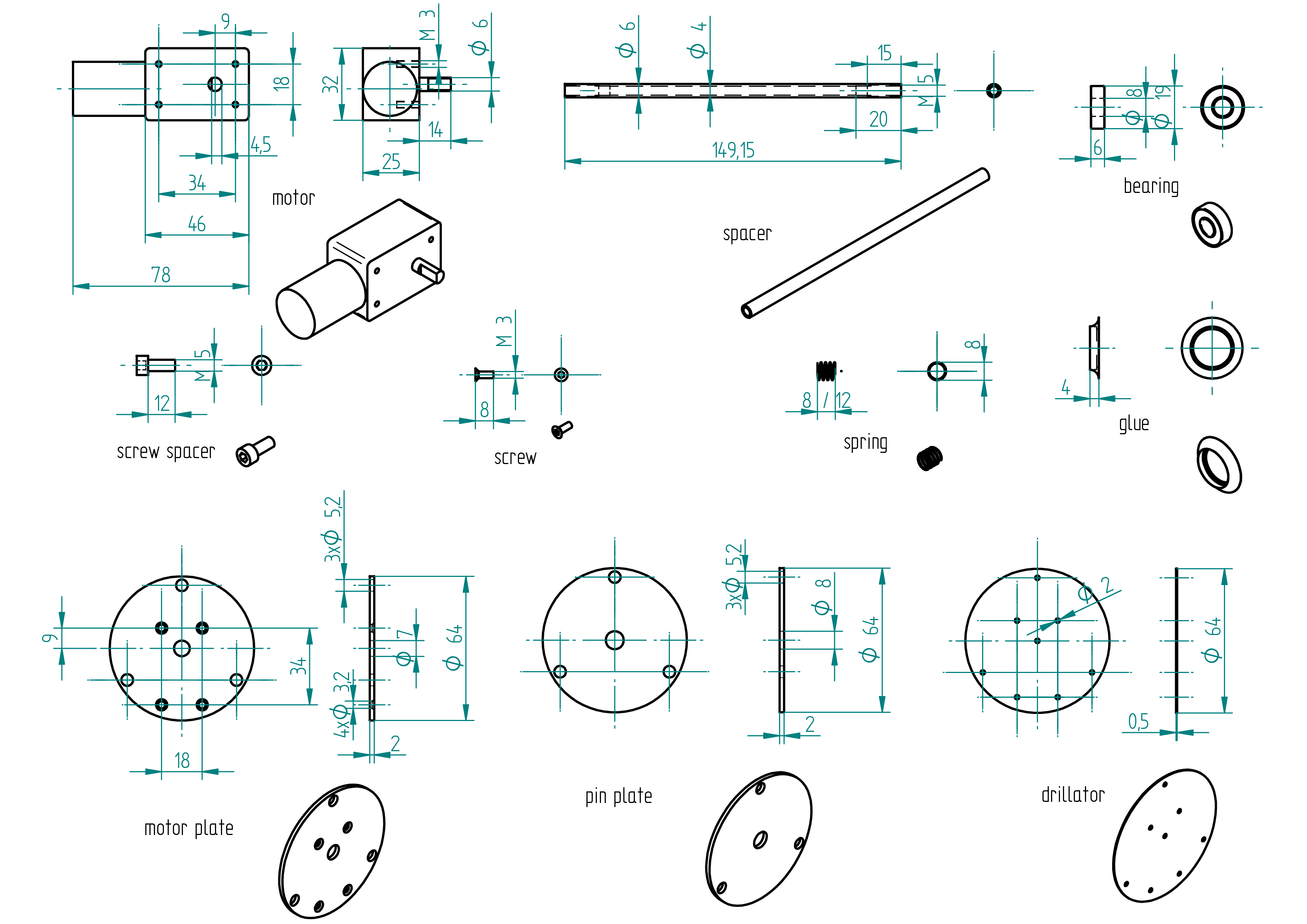
power unit p
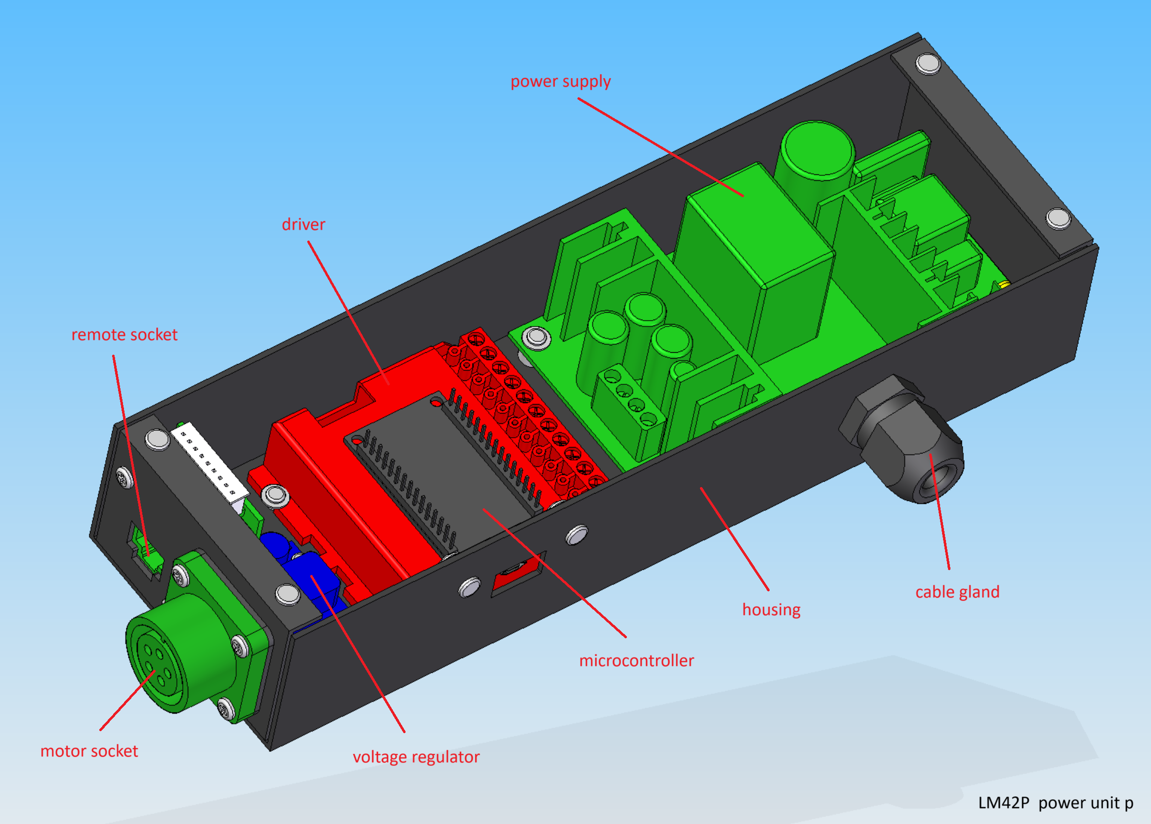
Parts list
| Qty | Part | Description | Material |
|---|---|---|---|
| 1 | housing | 78 x 47 x 240 mm | aluminium |
| 1 | power supply | 110V/220V 36V 180W | - |
| 1 | driver | G201X Digital Step Drive | - |
| 1 | microcontroller | ESP32 30 pins | - |
| 1 | voltage regulator | LM2596 | - |
| 1 | motor socket | amphenol female 5 poles | aluminium |
| 1 | remote socket | 34 x 28 x 18 mm RJ45 | - |
| 1 | cable gland | 17 x 34 x 8 mmm | - |
| 1 | motor plug | amphenol male 5 poles | aluminium |
| 1 | power supply cable | 3-core 0.5mm2 length : 2 m | - |
| 1 | power supply plug | depends on country 110 V or 220 V | - |
| 1 | motor cable | 4-cores 0.5mm2 length : 1 m ( in case the motor is not supplied with its own) | |
| 1 | wire | 0.5mm2 length : 1 m | cooper |
| 1 | wire | 0.75mm2 length : 0.50 m | cooper |
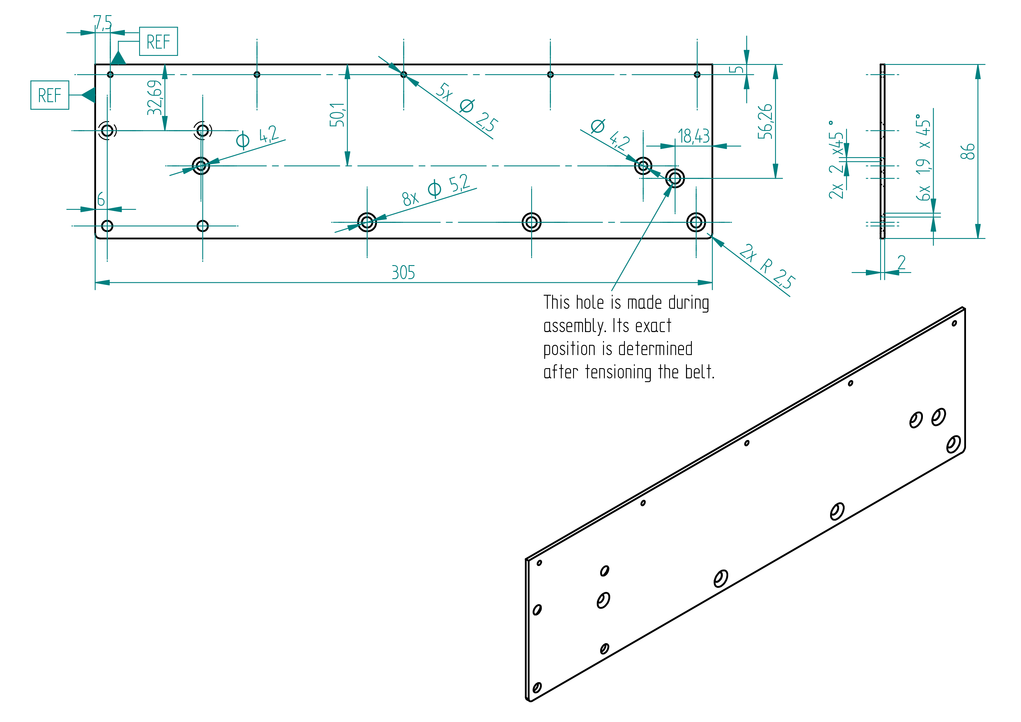
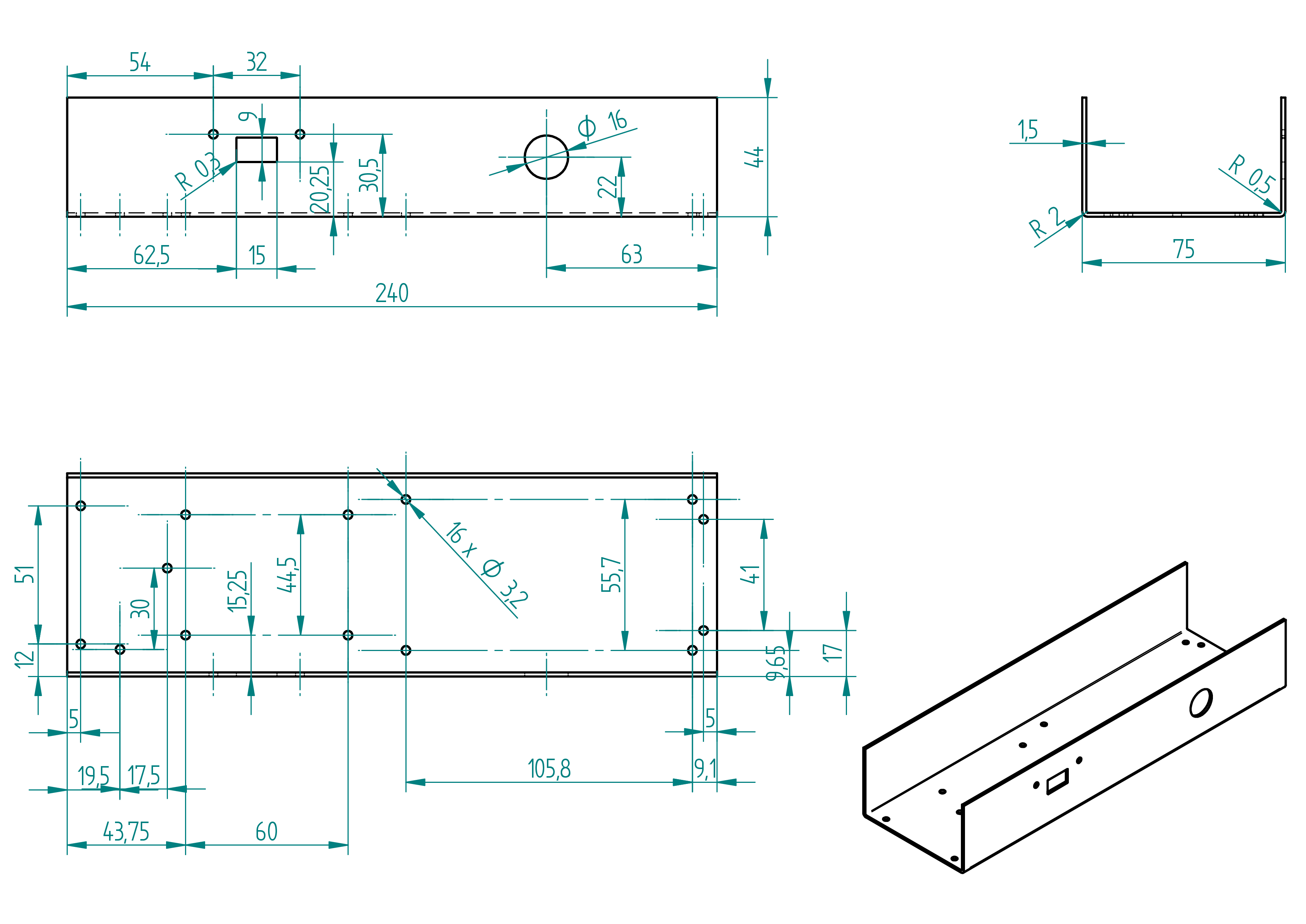
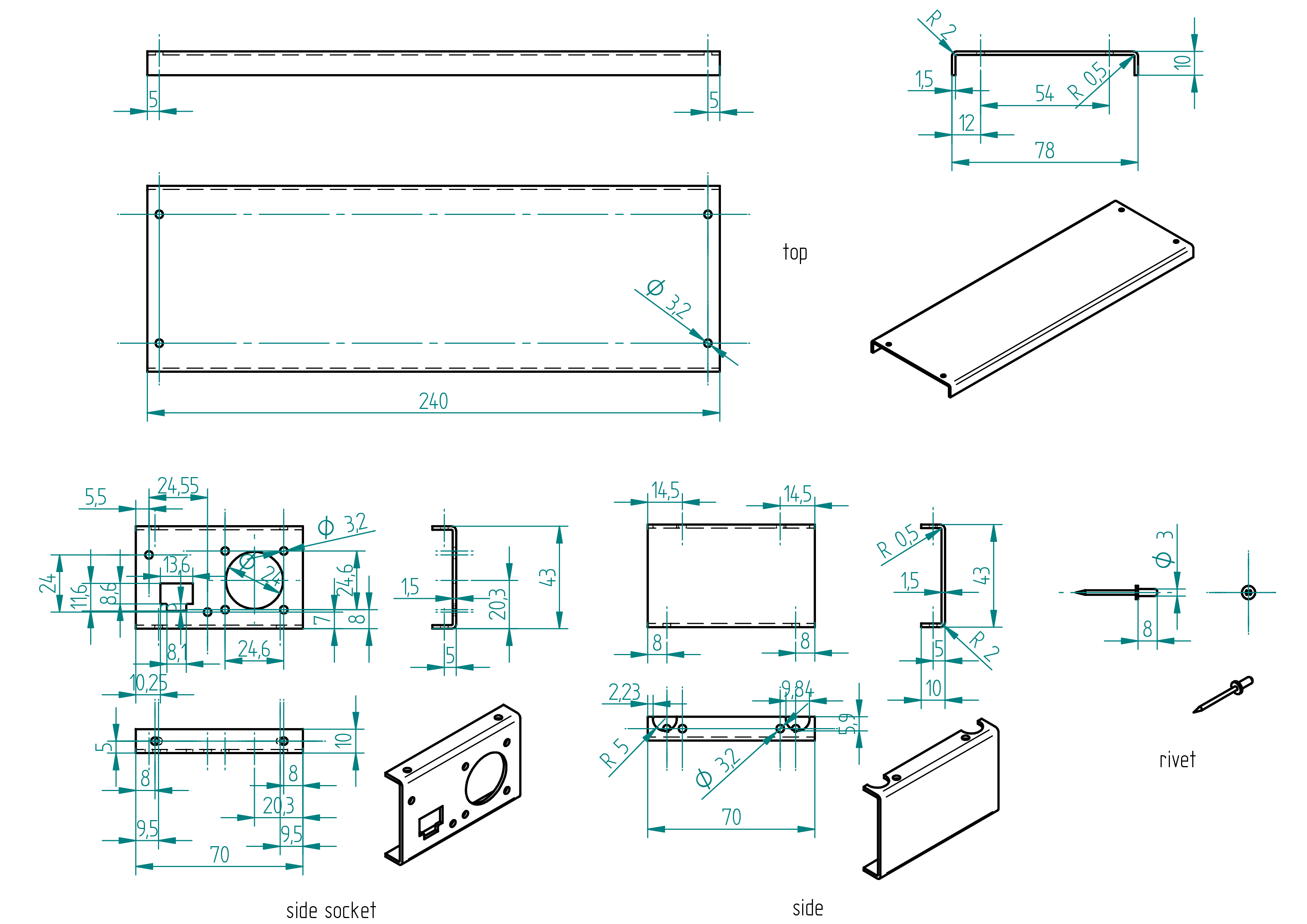
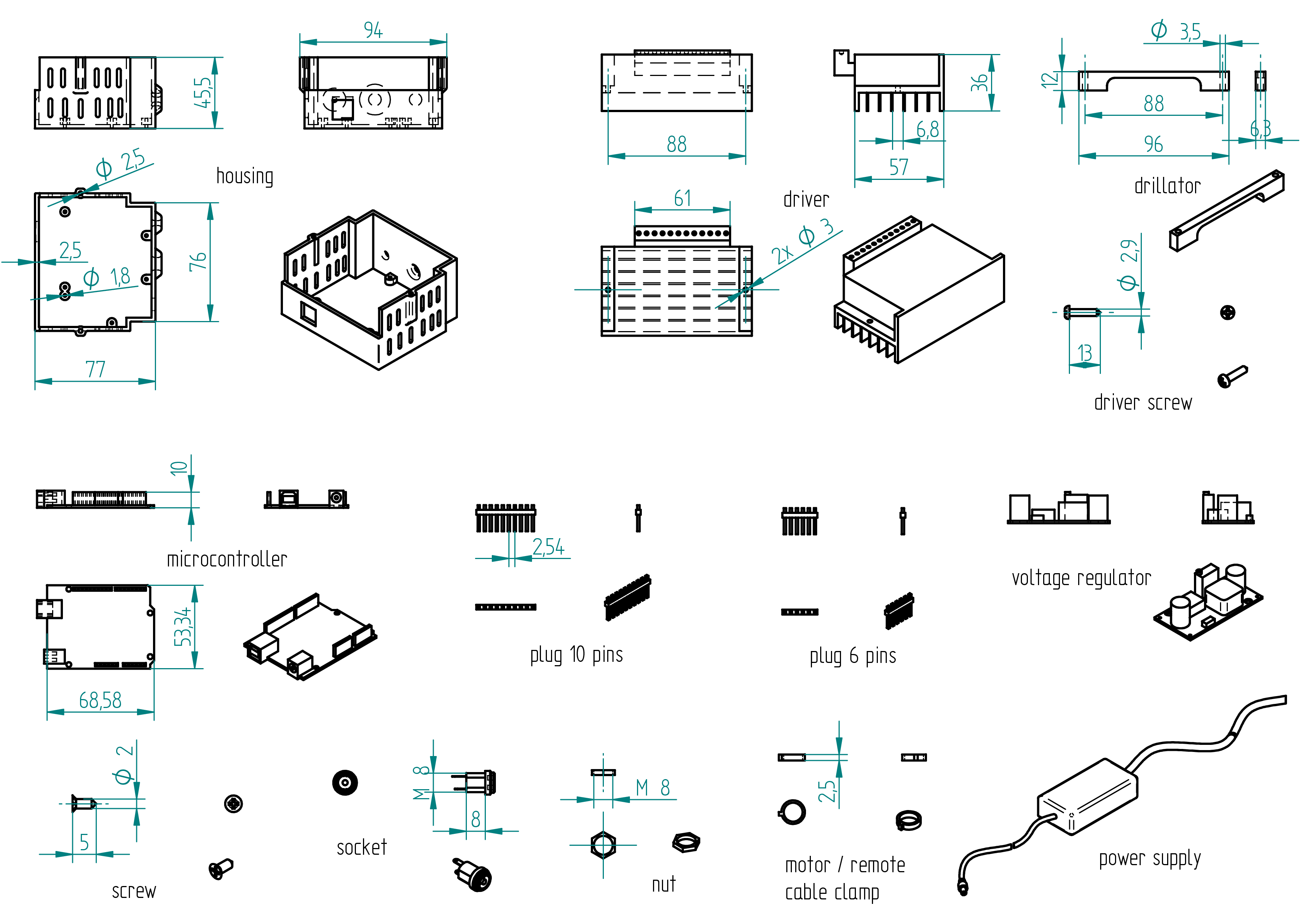
housing
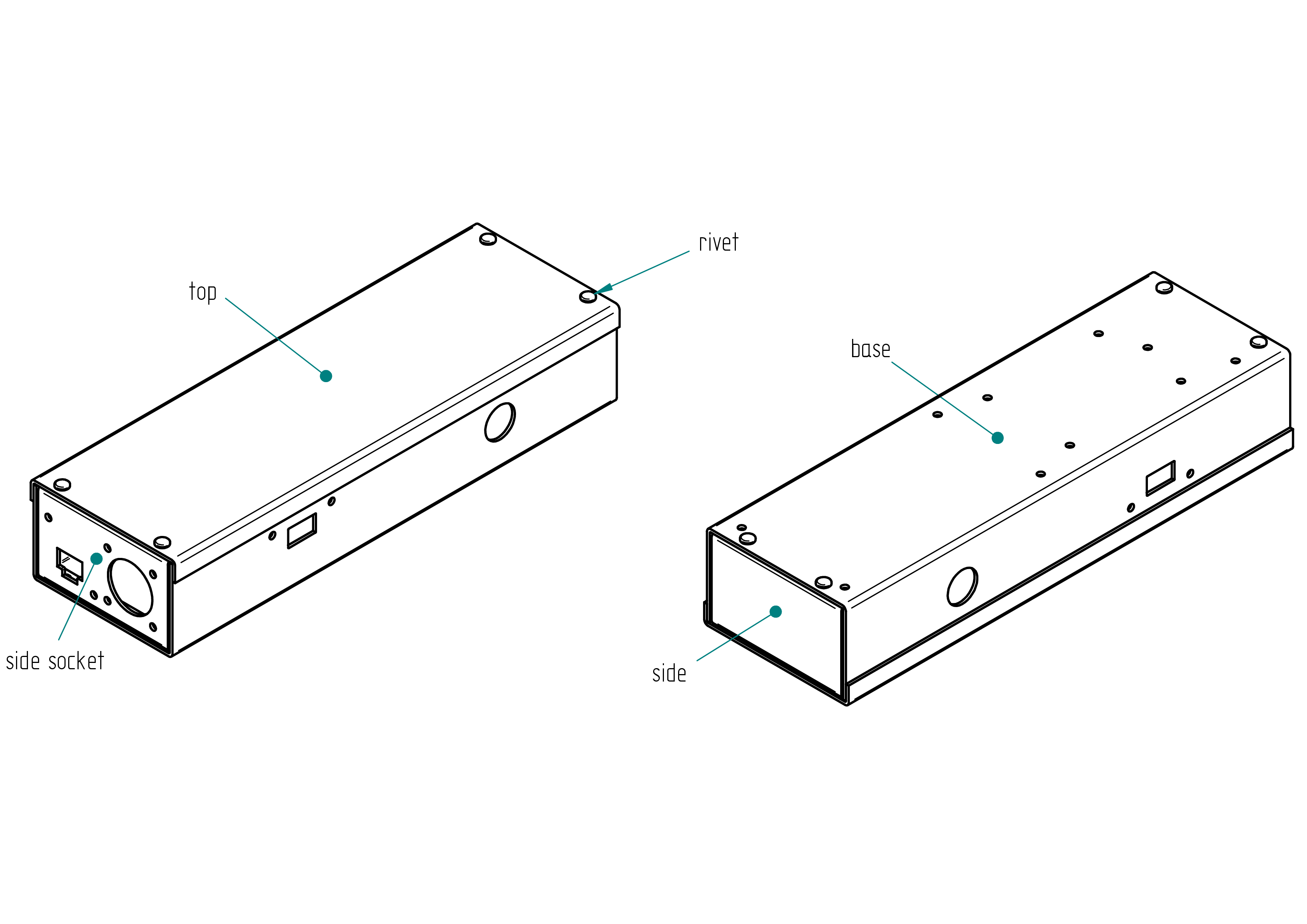
Parts list
| Qty | Part | Description | Material |
|---|---|---|---|
| 1 | base | U 75 x 44 x 1.5 length : 240 mm | aluminium |
| 1 | top | U 78 x 10 x 1.5 length : 240 mm | aluminium |
| 1 | side socket | U 43 x 10 x 1.5 length : 70 mm | aluminium |
| 1 | side | U 43 x 10 x 1.5 length : 70 mm | aluminium |
| 8 | rivet | 3 x 8 mm | aluminium |
Drawing
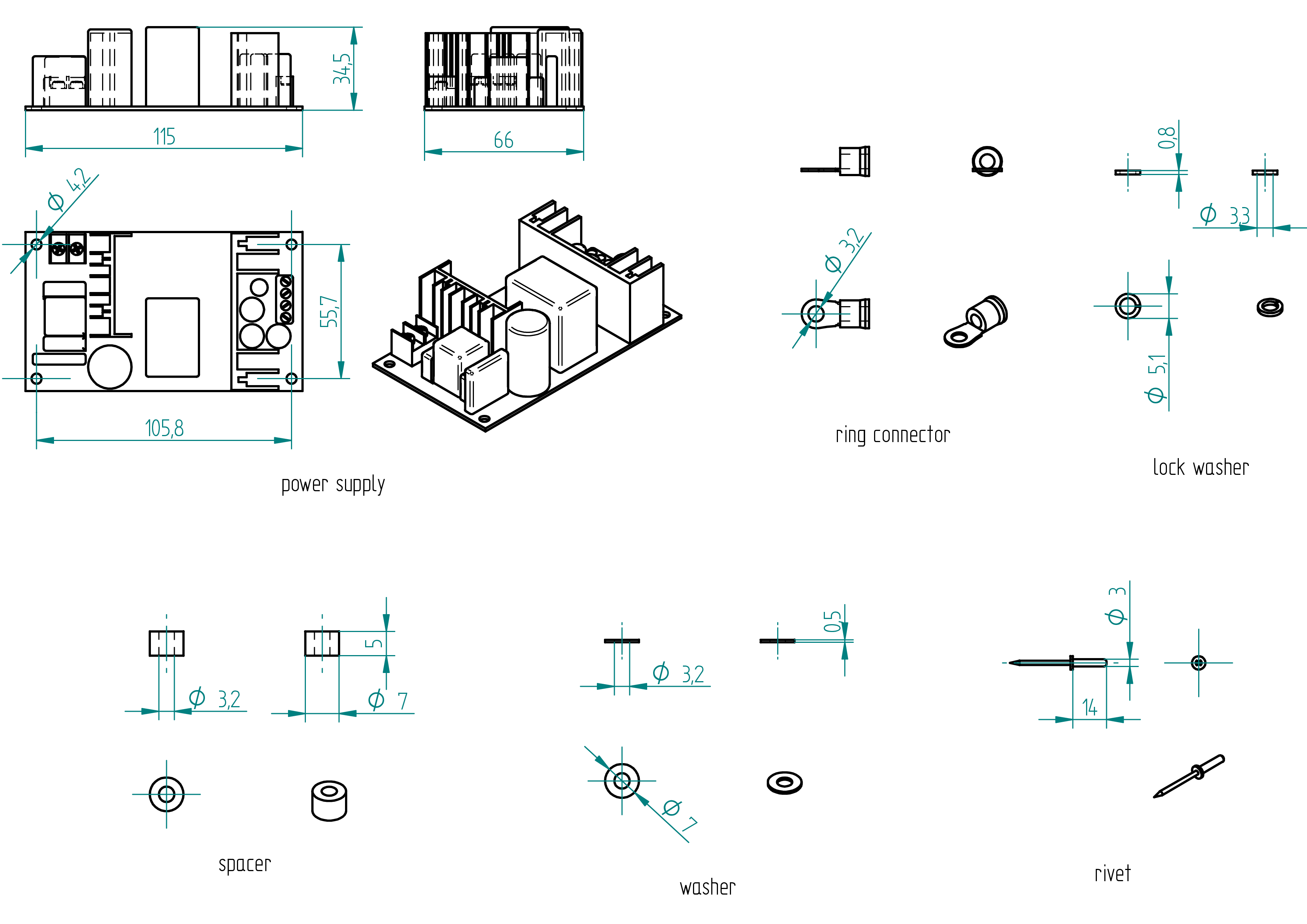
power supply
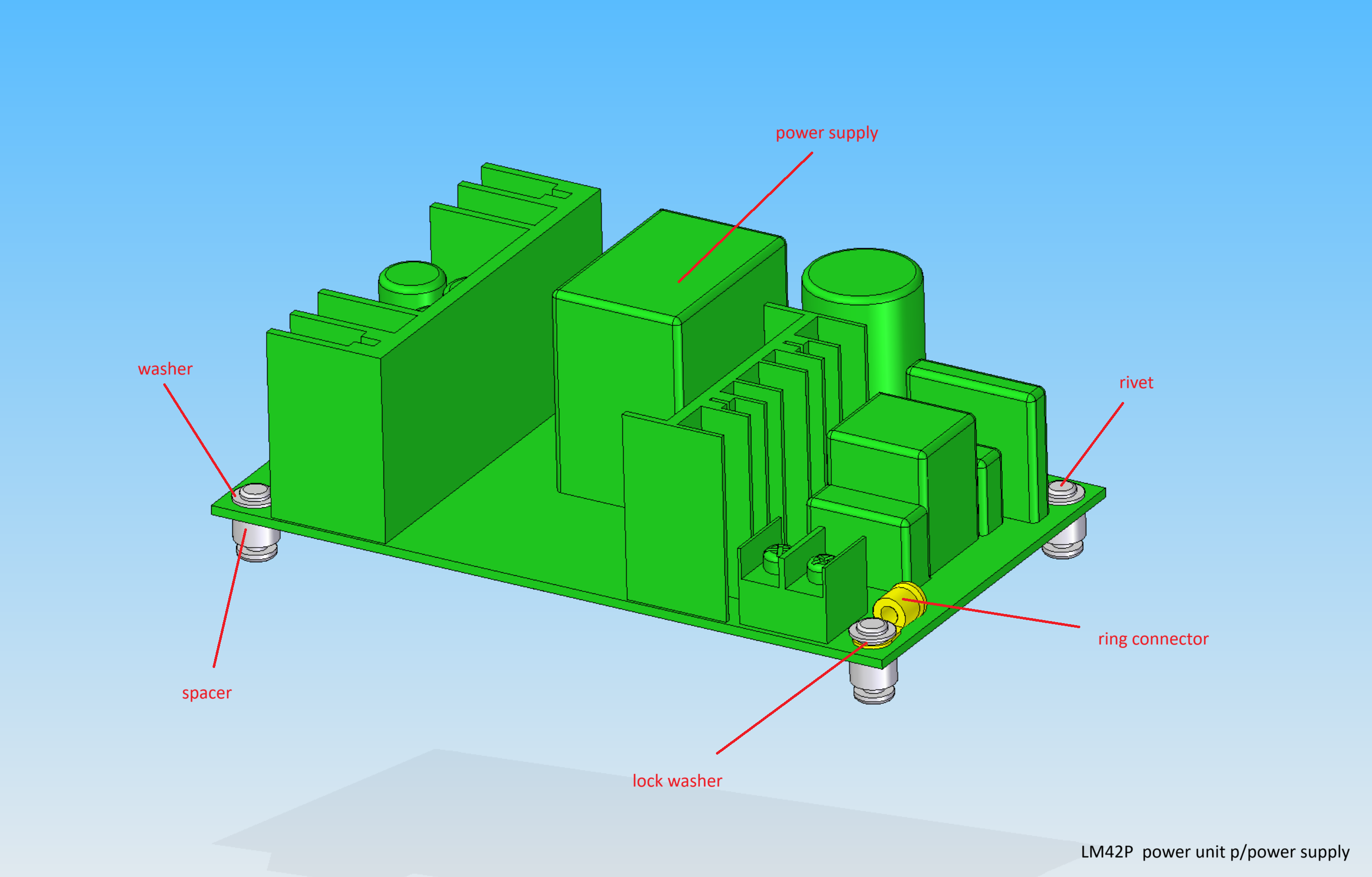
Parts list
| Qty | Part | Description | Material |
|---|---|---|---|
| 1 | power supply | AC/DC WXDC2416 220-110/36V | - |
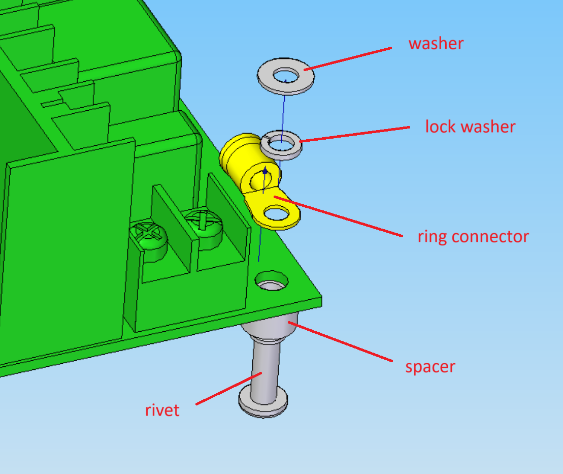
| 1 | ring connector | M3 | - |
| 1 | lock washer | 3.3 x 5.1 x 0.8 | stainless steel |
| 4 | spacer | 3.2 x 7 x 5 | aluminium |
| 4 | washer | 3.2 x 7 x 0.5 | stainless steel |
| 4 | rivet | 3 x 14 mm | aluminium |
Drawing
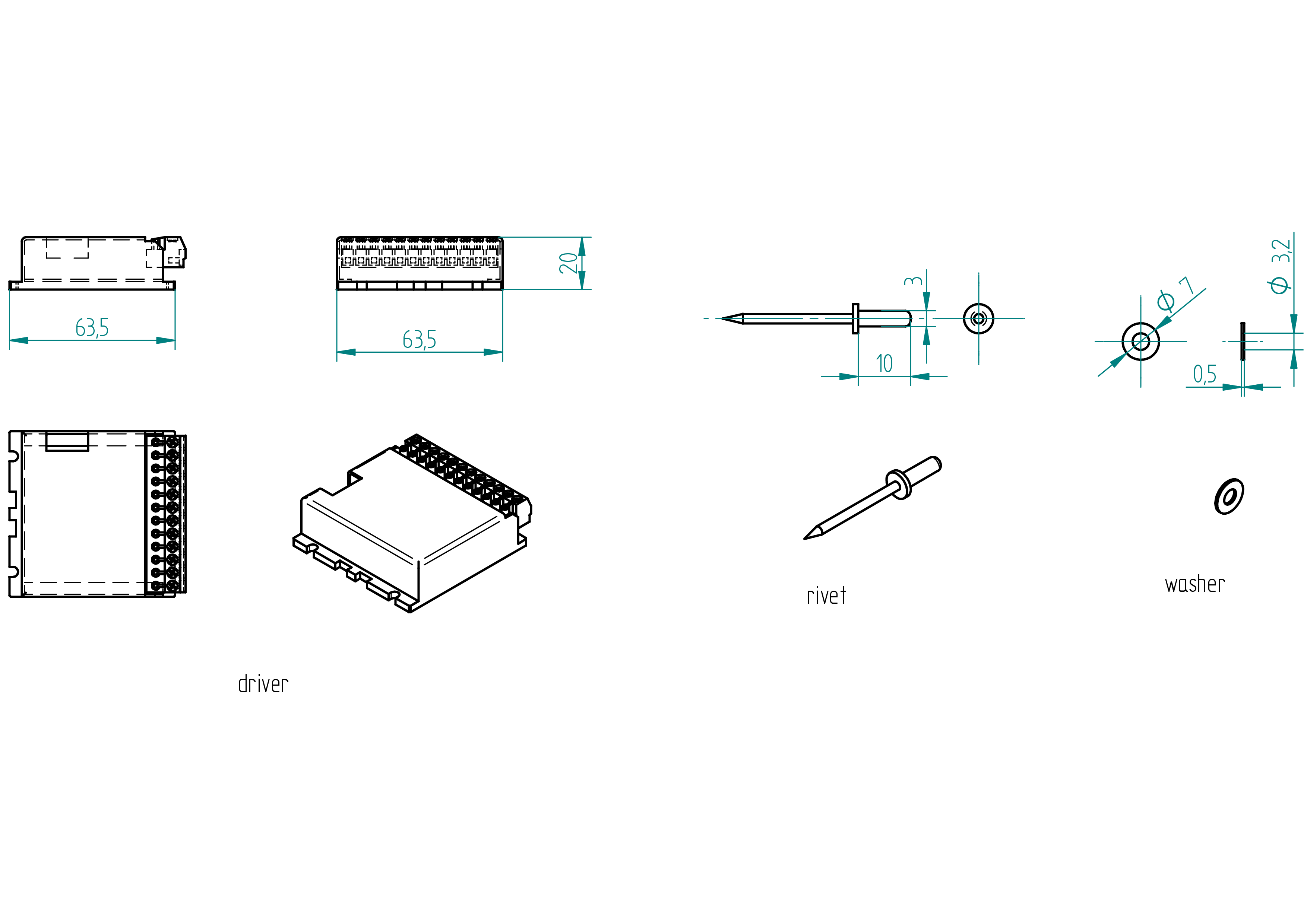
driver
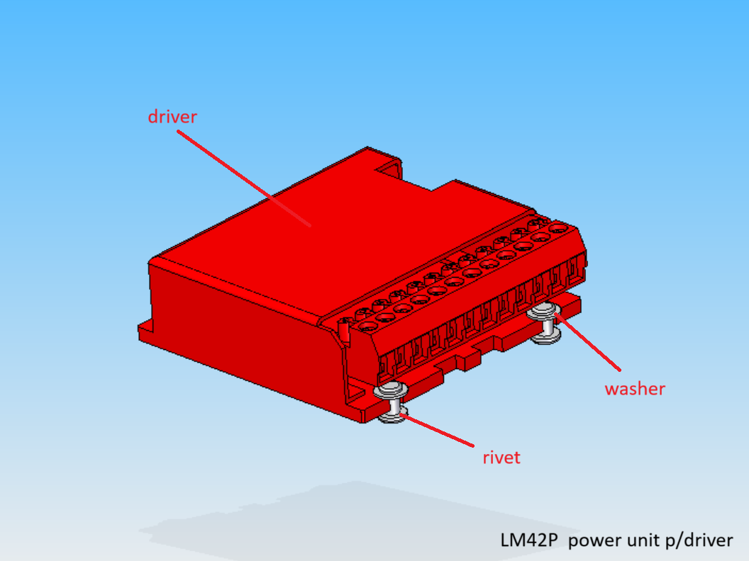
Parts list
| Qty | Part | Description | Material |
|---|---|---|---|
| 1 | driver | G201X Digital Step Drive | - |
| 4 | washer | 3.2 x 7 x 0.5 | stainless steel |
| 4 | rivet | 3 x 10 mm | aluminium |
Drawing
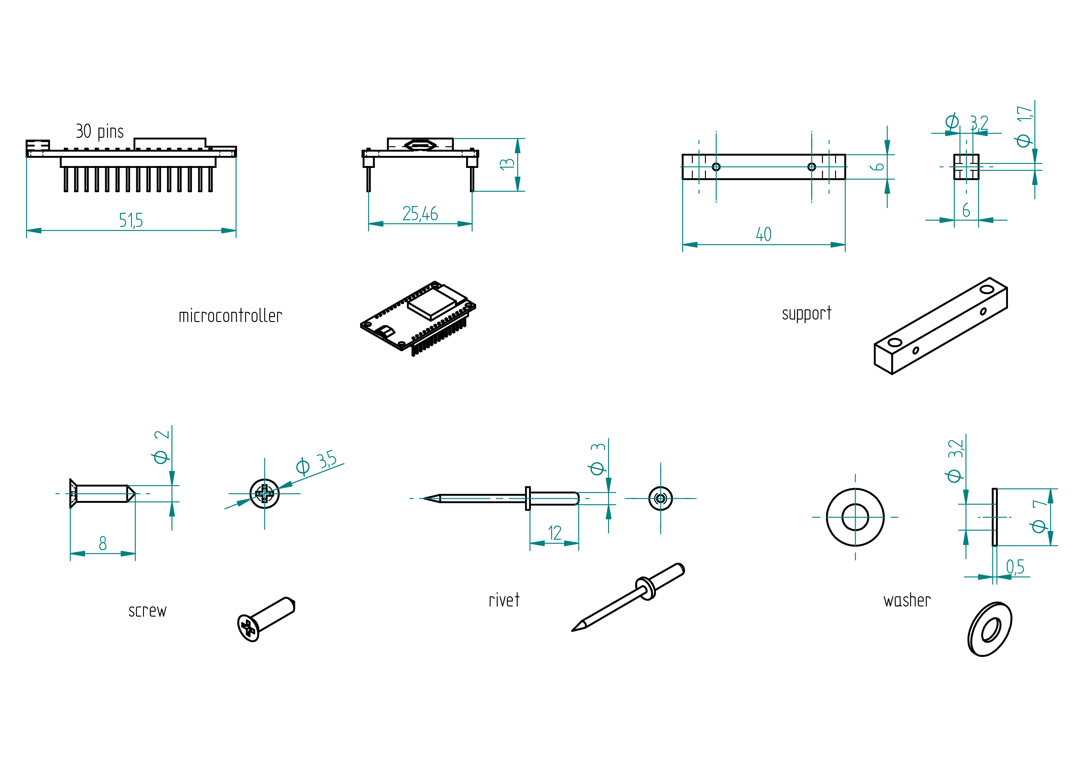
microcontroller
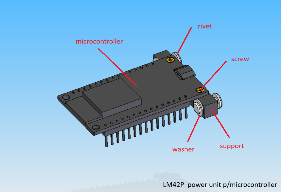
Parts list
| Qty | Part | Description | Material |
|---|---|---|---|
| 1 | microcontroller | ESP32 30 pins | - |
| 1 | support | 3D printed | PLA |
| 2 | screw | 2 x 8 | brass |
| 2 | washer | 3.2 x 7 x 0.5 | stainless steel |
| 2 | rivet | 3 x 12 mm | aluminium |
Drawing
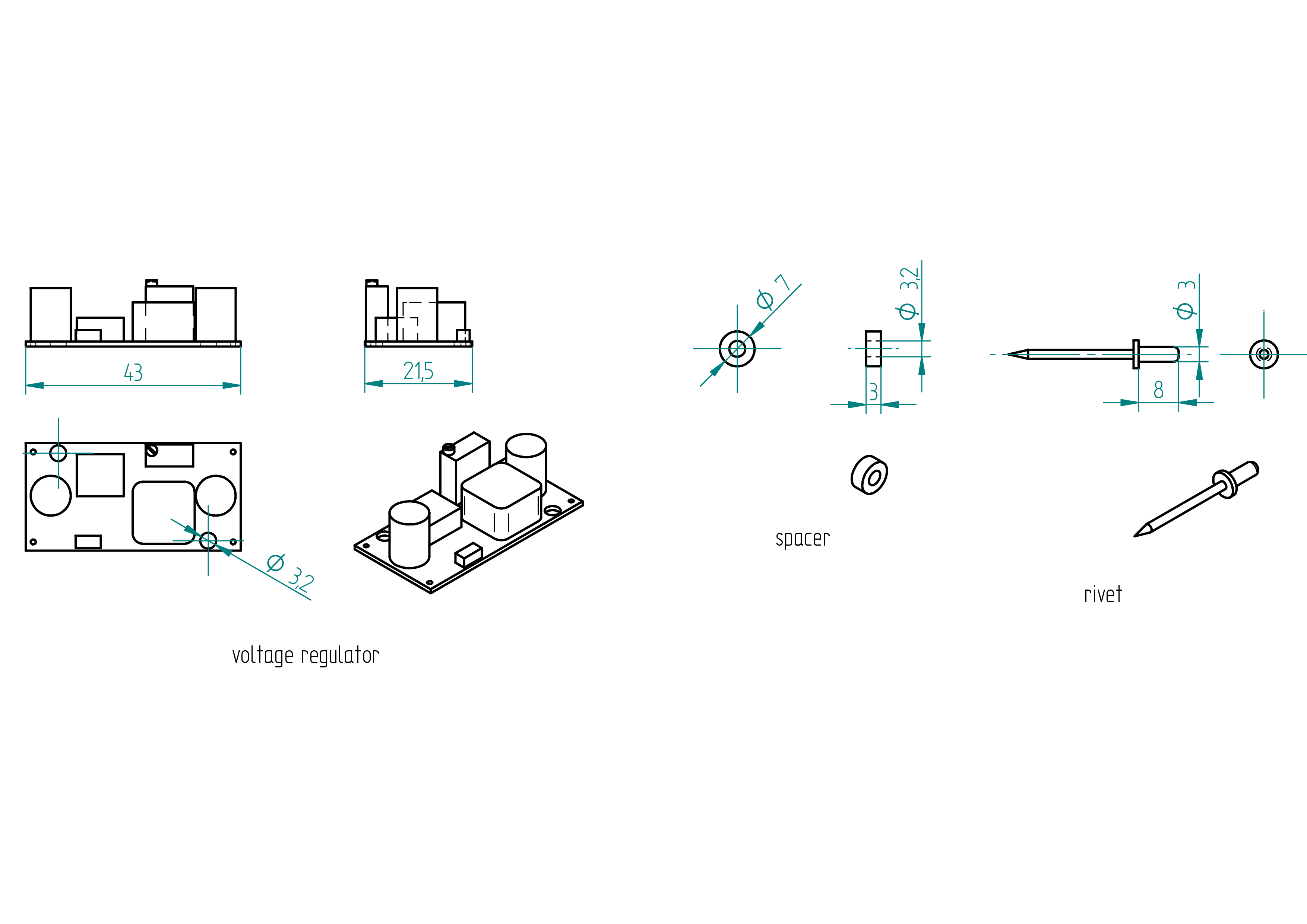
voltage regulator
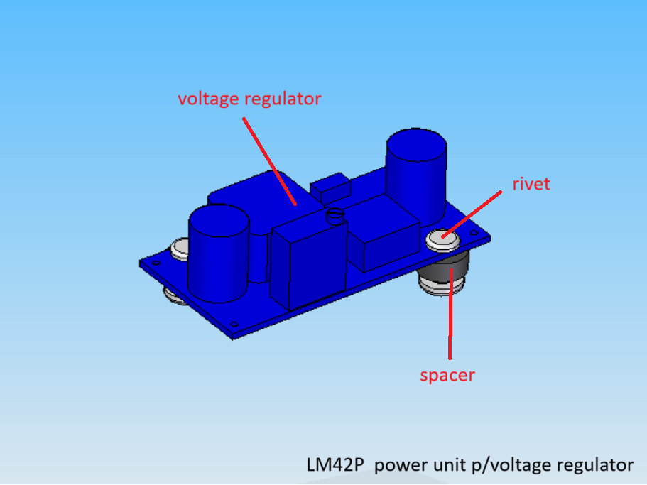
Parts list
| Qty | Part | Description | Material |
|---|---|---|---|
| 1 | voltage regulator | LM2596 | - |
| 2 | spacer | 3.2 x 7 x 3 | nylon |
| 2 | rivet | 3 x 8 mm | aluminium |
Drawing
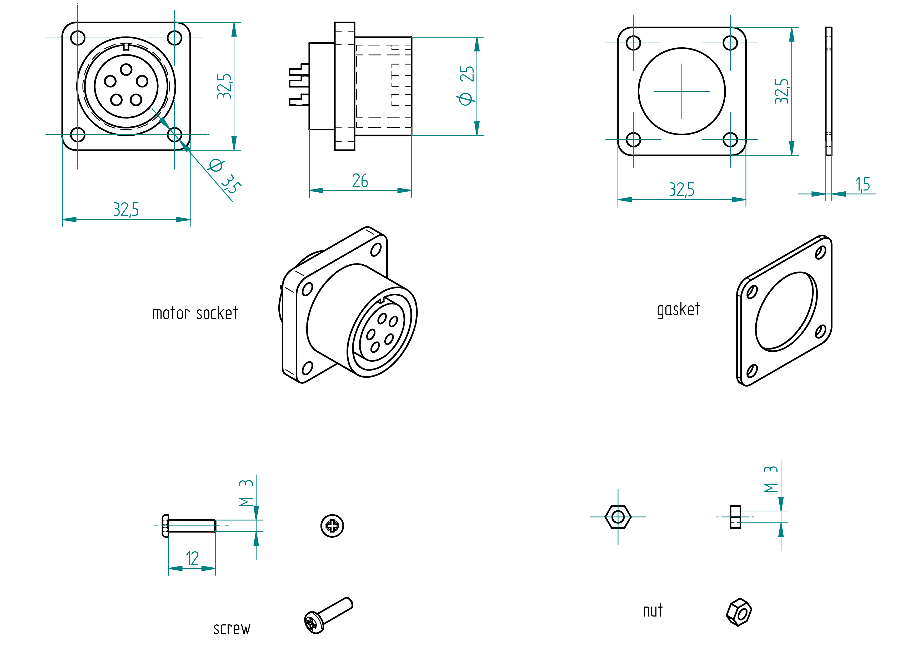
motor socket
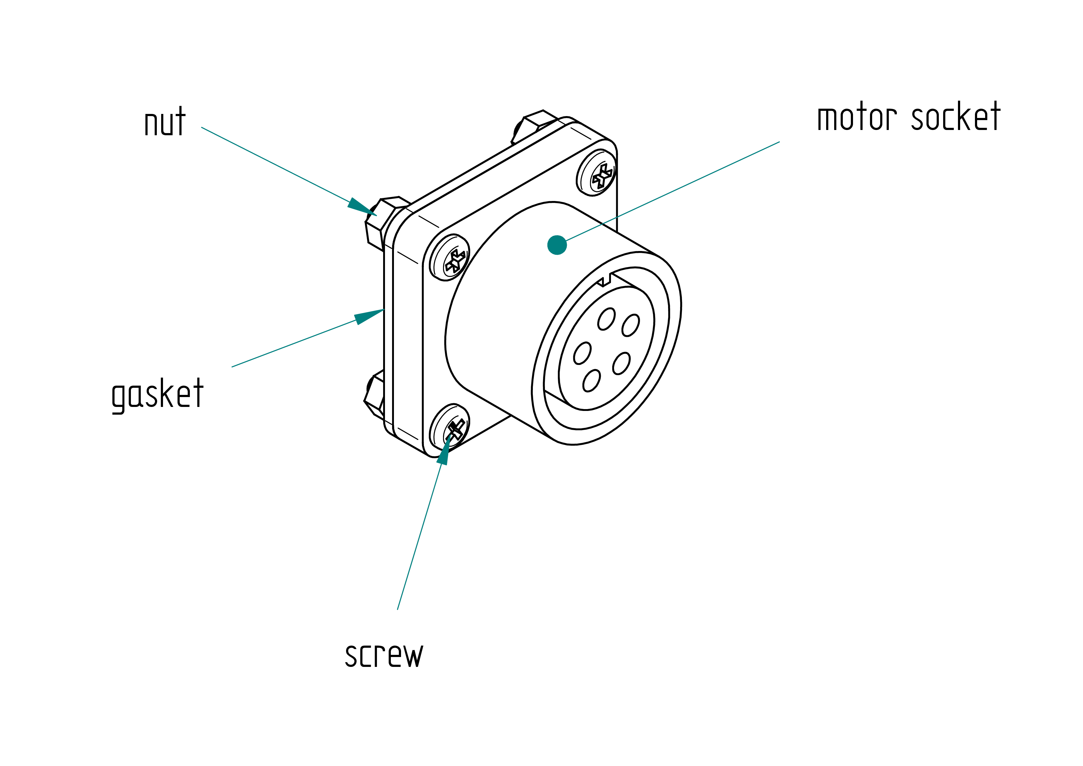
Parts list
| Qty | Part | Description | Material |
|---|---|---|---|
| 1 | motor socket | amphenol female 5 poles | aluminium |
| 1 | gasket | 32.5 x 32.5 x 1.5 | rubber |
| 4 | screw | M3 x 12 mm | stainless steel |
| 4 | nut | M3 | stainless steel |
Drawing
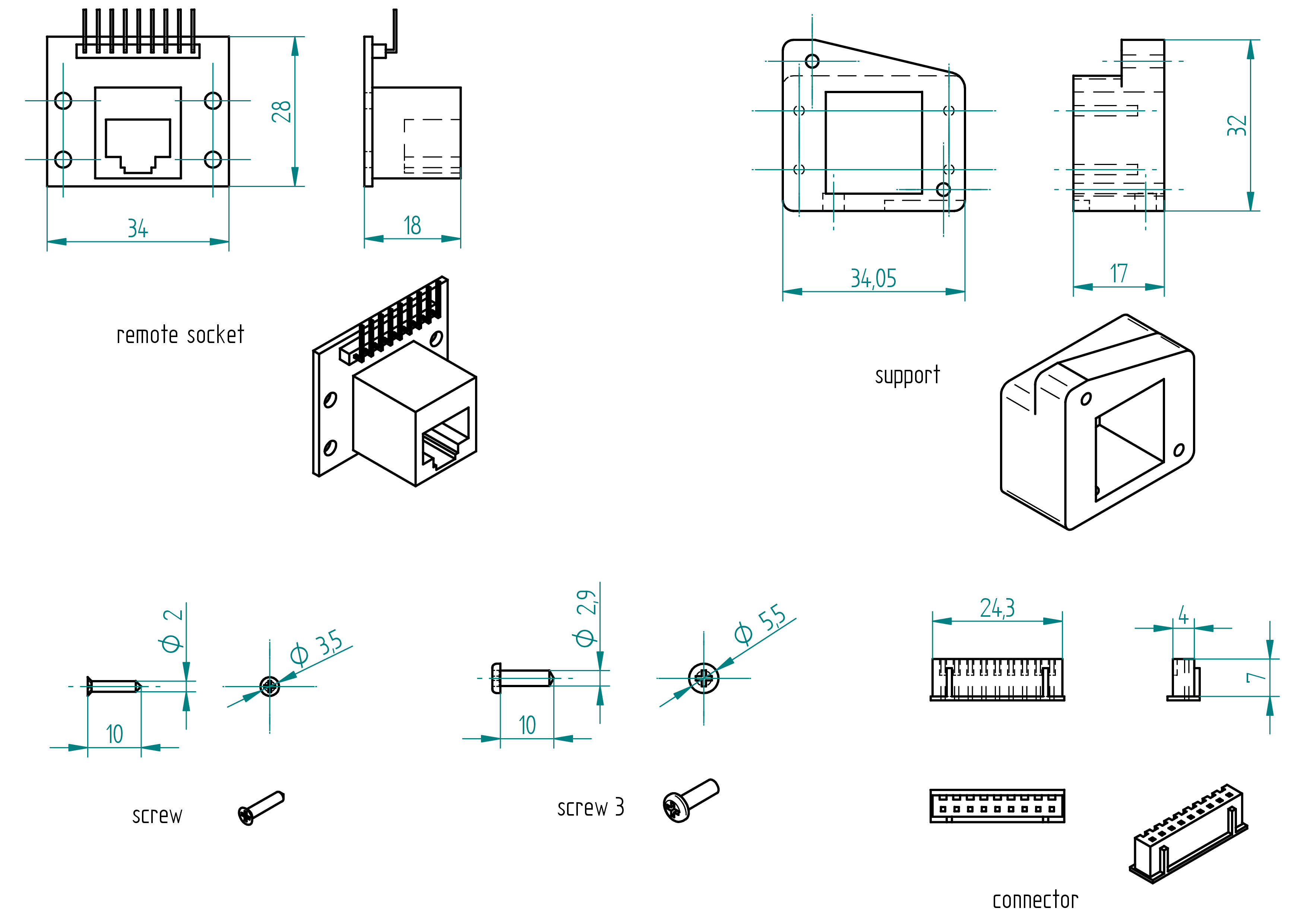
remote socket
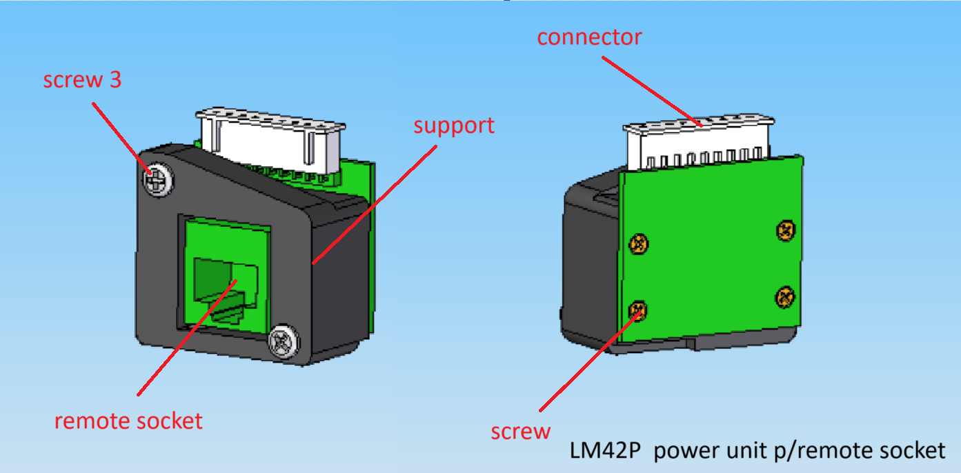
Parts list
| Qty | Part | Description | Material |
|---|---|---|---|
| 1 | remote socket | 34 x 28 x 18 RJ45 | - |
| 1 | support | 3D printed | PLA |
| 4 | screw | 2 x 10 mm | brass |
| 2 | screw 3 | 2.9 x 10 mm | stainless steel |
| 2 | connector | 24.3 x 7 x 4 mmm 9 poles | - |
Drawing
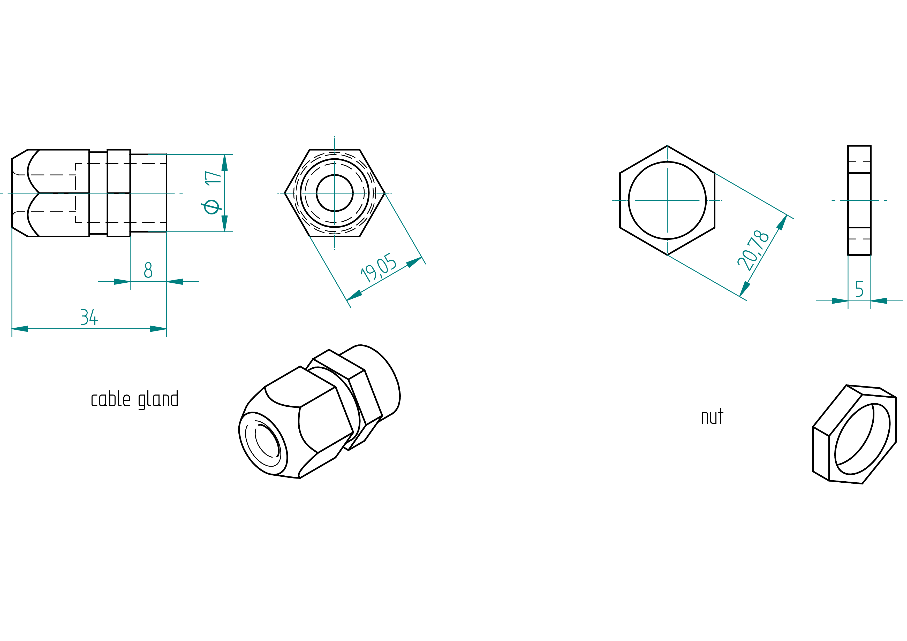
cable gland
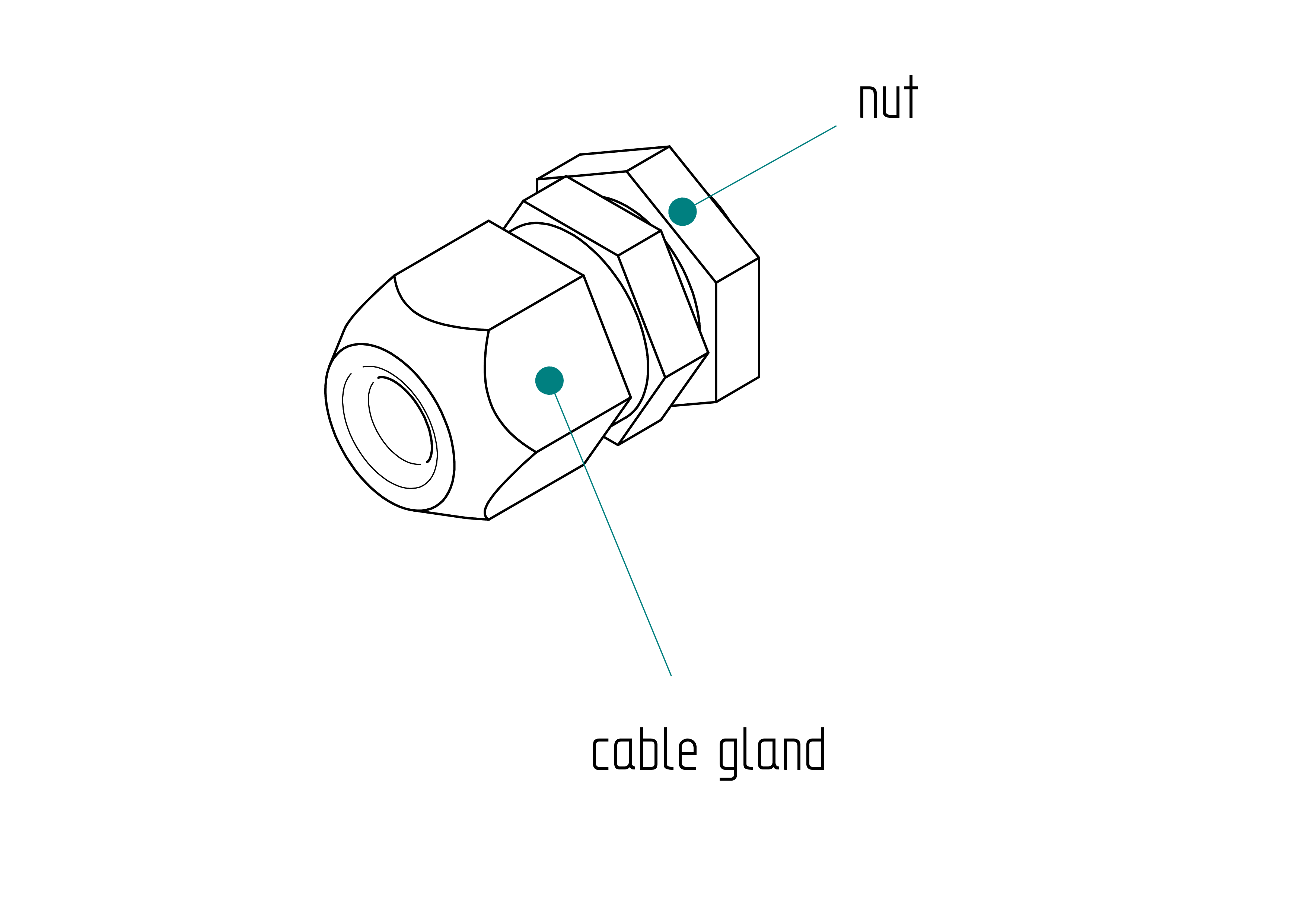
Parts list
| Qty | Part | Description | Material |
|---|---|---|---|
| 1 | cable gland | 17 x 34 x 8 mm | nylon |
| 1 | nut | 17 x 5 mm | nylon |
Drawing
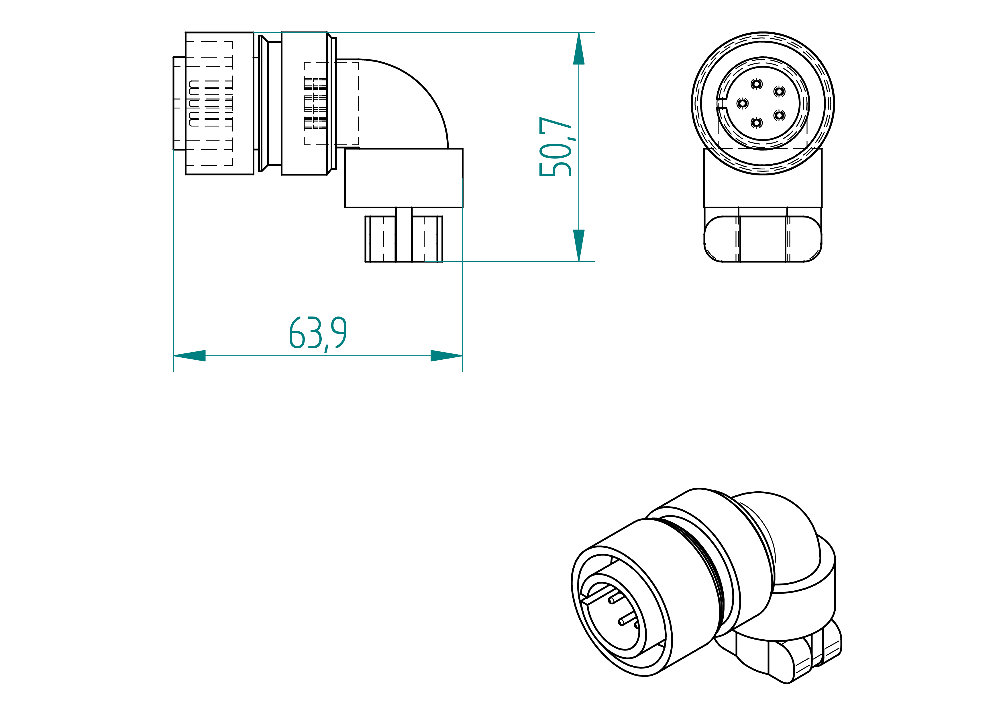
motor plug
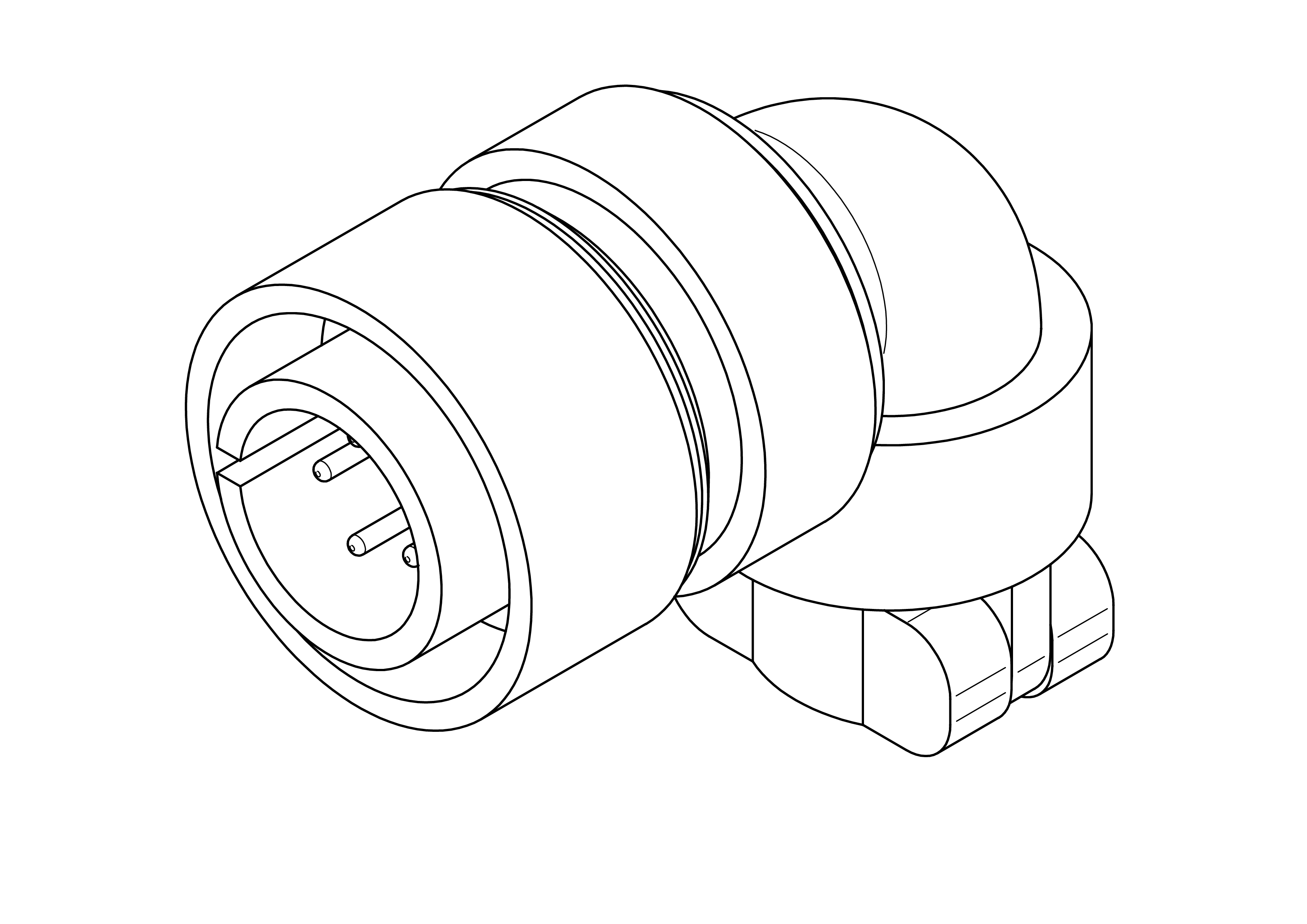
Parts list
| Qty | Part | Description | Material |
|---|---|---|---|
| 1 | motor plug | amphenol male 5 poles | aluminium |
Drawing
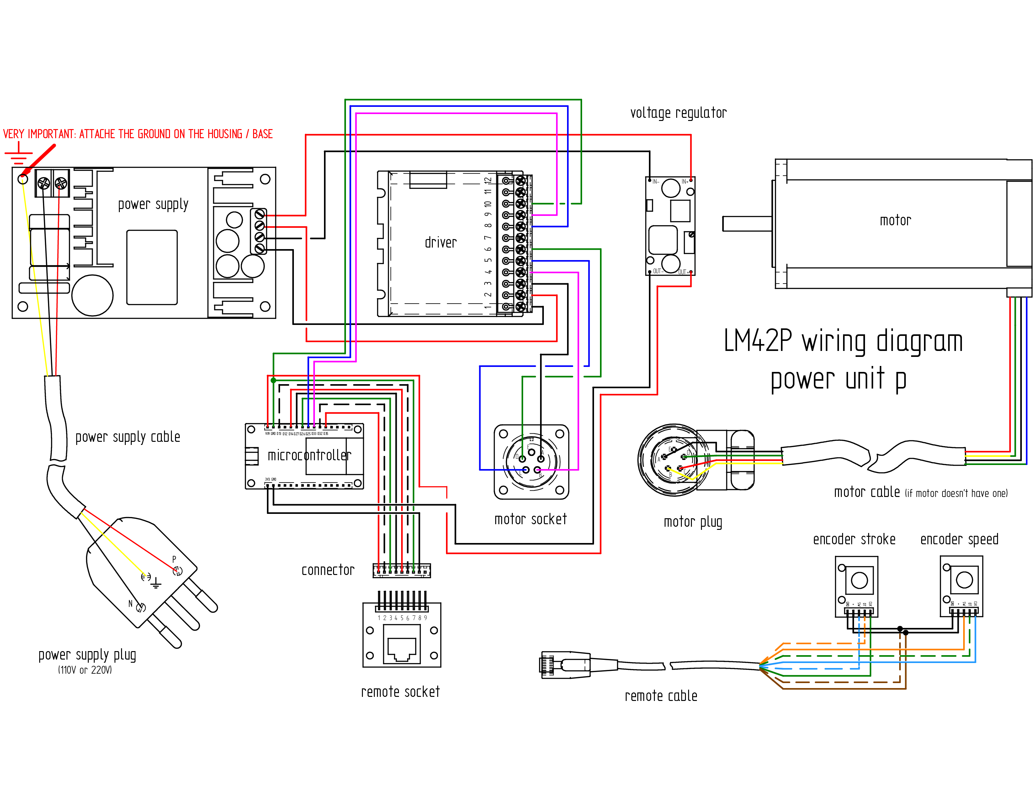
Wiring
Wiring diagram
Parts list
| Qty | Part | Description | Material |
|---|---|---|---|
| 1 | power supply cable | 3 poles 0.75mm2 length : 2 m | - |
| 1 | power supply plug | depends on country 110 V or 220 V | - |
| 1 | motor cable | 4 poles 0.5mm2 length : 1 m ( If the motor is not supplied with its own cable, refer to the Appendix, for instructions on how to attach it.} | |
| 1 | wire | 0.5mm2 length : 1 m | cooper |
| 1 | wire | 0.75mm2 length : 0.50 m | cooper |
Required Tools and Components
- 1x wire cutter ;
- 1x wire stripper ;
- 1x terminal crimping tool ;
- 1x multimeter ;
- 1x soldering iron ;
- 1x solder ;
- 1x gauge ;
- 1x screwdriver 0 ;
- 1x rivet gun ;
- 1x water pump pliers ;
- 1x electrical tape.
Wiring Instructions
The lengths and cross-sectional areas of the wires are listed in table , page .
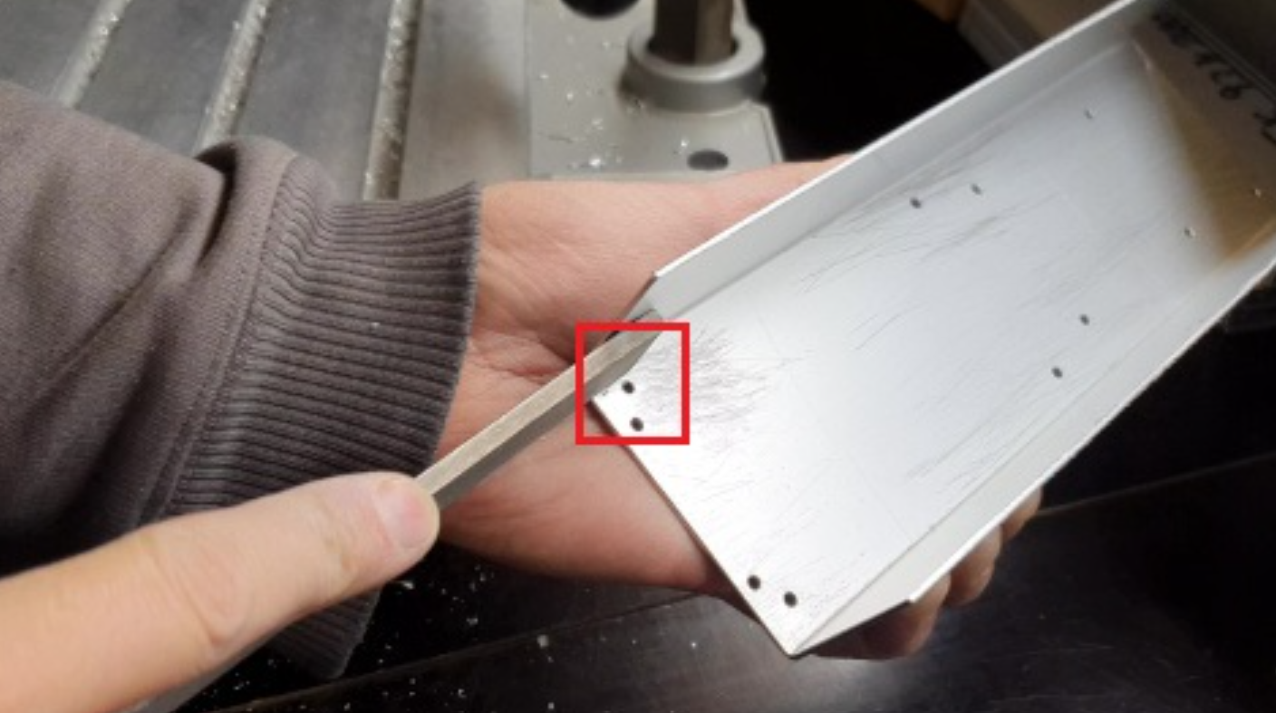
- File the bottom of the base (only the part where the red framed hole is) so that the grounding contact faces well. This operation is not necessary if you are using non anodized sheets (anodized surfaces are none-conductive). .
- Strip the power supply cable 3 cores at 10cm.
- Tighten the ring connector on the ground wire (yellow).
- Fix the cable gland to the base.
- Tighten cable gland.
- Control the power supply : control the voltage of the output of the power supply with a voltmeter. It should be 36V.
- Install the power supply in the base, ensuring that the ground connection is correctly made ().
- Connect and tighten the phase and neutral wires to the 36V "IN" terminals of the power supply.
- Connect the power supply plug to the power supply cable.
- Use a multimeter (in resistance mode) to verify that the ground of the power supply plug is properly connected to the base.
- Solder the four wires to the corresponding pins on the voltage regulator :
- Connect the wire to IN+ (input positive).
- Connect the wire to IN- (input negative).
- Connect the wire to OUT+ (output positive).
- Connect the wire to OUT- (output negative).
- Install the voltage regualator in the base.
- Adjust voltage regulator voltage :
- Connect the voltage regulator IN to the power supply OUT ;
- Connect the voltmeter to voltage regulator OUT
- Solder the four wires to the motor socket.
- Install all other components in the base.
- Wire them properly (see Terminals Connection and Wires details in Table , page and Wiring diagram , ).
- If the motor does not already have a cable installed, solder four wires to the motor. See Appendix: Attach the motor cable , page , for instructions on how to attach it. (It is much easier if you can get a motor with the cable already wired.)
- Wire the motor plug :
- Strip the outer cable sheath over a length of 3 cm.
- Strip the four inner wires and solder them as required.
- At 5 cm from the edge, wrap 10 layers of electrical tape around the cable.
- Soldered the four wires as follows ("Actually, this is not the same as shown in the ESP schematic. I connected the M2 according to the table, but next time I need to follow the ESP schematic and check whether the red and green sides of the machine are the same.") : * red → C ; * green → B ; * black → A ; * blue → D.
- Assemble the plug and tighten the flange.
- Wire the remote-d.
Terminals Connections and Wires details
| Qty | Part | Description | Material |
|---|---|---|---|
| D35_microcontroller - 1_connector | 9 | 0.25 | |
| D32_microcontroller - 2_connector | 9 | 0.25 | |
| D33_microcontroller - 9_driver | 9 | 0.25 | |
| D25_microcontroller - 8_driver | 9 | 0.25 | |
| D26_microcontroller - 3_connector | 9 | 0.25 | |
| D27_microcontroller - 4_connector | 9 | 0.25 | |
| D14_microcontroller - 5_connector | 9 | 0.25 | |
| D13_microcontroller - 6_connector | 9 | 0.25 | |
| 10_driver - 7_connector | 15 (don't cut) | 0.25 | |
| 10_driver - GND_microcontroller | 9 (Wired according to precedent and tightly bundled within the 10_driver) | 0.5 | |
| 3_driver - A_motor socket | 15 | 0.75 | |
| 4_driver - B_motor socket | 15 | 0.75 | |
| 5_driver - C_motor socket | 15 | 0.75 | |
| 6_driver - D_motor socket | 15 | 0.75 | |
| 8_connector - VIN_microcontroller | ? | 0.25 | |
| OUT-_voltage regulator - GND_microcontroller | 7 | 0.5 | |
| OUT+_voltage regulator - VIN_microcontroller | 12 | 0.5 | |
| IN+_voltage regulator - OUT+_power supply | 16 | 0.5 | |
| IN-_voltage regulator - OUT-_power supply | 15 | 0.5 |
Firmware
After all components have been installed and wired inside the housing, it is time to upload the firmware to the microcontroller.
m1
The firmware source code for machine m1 is located in the
**firmware** directory. A portion of the firmware code
is shown below.
To upload the firmware, please follow the steps described in the Appendix.
//speed rotary encoder
#define ROTARY_ENCODER_A_PIN 27 //CLK
#define ROTARY_ENCODER_B_PIN 26 //DT
#define ROTARY_ENCODER_BUTTON_PIN 32 //SW
#define ROTARY_ENCODER_STEPS 4
#define ROTARY_ENCODER_ACCELERATION 2000 //30000 3000
AiEsp32RotaryEncoder rotaryEncoder = AiEsp32RotaryEncoder(ROTARY_ENCODER_A_PIN, ROTARY_ENCODER_B_PIN, ROTARY_ENCODER_BUTTON_PIN, -1, ROTARY_ENCODER_STEPS);
// stroke rotary encoder
#define ROTARY_ENCODER2_A_PIN 13 //CLK
#define ROTARY_ENCODER2_B_PIN 35 //DT
#define ROTARY_ENCODER2_BUTTON_PIN 14 //SW
#define ROTARY_ENCODER2_STEPS 4
#define ROTARY_ENCODER2_ACCELERATION 7000
AiEsp32RotaryEncoder rotaryEncoder2 = AiEsp32RotaryEncoder(ROTARY_ENCODER2_A_PIN, ROTARY_ENCODER2_B_PIN, ROTARY_ENCODER2_BUTTON_PIN, -1, ROTARY_ENCODER2_STEPS);
void IRAM_ATTR readEncoderISR()
{
rotaryEncoder.readEncoder_ISR();
rotaryEncoder2.readEncoder_ISR();
}
// IO pin assignments
const int MOTOR_STEP_PIN = 33;
const int MOTOR_DIRECTION_PIN = 25;
// Speed and stroke settings
const int MIN_SPEED = 2000; //set min speed in us/step
const int MAX_SPEED = 10; // no diff 5 and 20 5 10 15 25 45 speed/accelration for 1kg toy: 45/320000
// higher the acceleration and lower value of speed can be set to be
// more speedy
const int MIN_STROKE = 10; // 10 vibro_stroke = 10
const int MAX_STROKE = 4800; //4850 4650 4600 4500 4000
// Motor acceleration
int MOTOR_ACCELERATION = 320000; // 640000 for small toy 850000 decroche 640000 320000; // speed/acceleration for 1kg toy: 45/320000
FastAccelStepperEngine engine = FastAccelStepperEngine();
FastAccelStepper *stepper = NULL;
long target = 0; // it's the target
int previousDirection = 1;
bool stopped = true; //machine stopped
unsigned long lastButtonPress = 0; // avoid rebounce when button is pressed
bool green = false; // green side of the machine is used
bool red = false; // red side of the machine is used
const int GAP = 50; // gap between the end of machine and mobile part;
void setup() {
Serial.begin(115200);
pinMode(ROTARY_ENCODER_A_PIN, INPUT_PULLUP);
pinMode(ROTARY_ENCODER_B_PIN, INPUT_PULLUP);
pinMode(ROTARY_ENCODER2_A_PIN, INPUT_PULLUP);
pinMode(ROTARY_ENCODER2_B_PIN, INPUT_PULLUP);
m2
The firmware source code for machine m2 is located in the
**firmware** directory. A portion of the firmware code
is shown below.
To upload the firmware, please follow the steps described in the Appendix.
//speed rotary encoder
#define ROTARY_ENCODER_A_PIN 27 //CLK
#define ROTARY_ENCODER_B_PIN 26 //DT
#define ROTARY_ENCODER_BUTTON_PIN 32 //SW
#define ROTARY_ENCODER_STEPS 4
#define ROTARY_ENCODER_ACCELERATION 2000 //30000 3000
AiEsp32RotaryEncoder rotaryEncoder = AiEsp32RotaryEncoder(ROTARY_ENCODER_A_PIN, ROTARY_ENCODER_B_PIN, ROTARY_ENCODER_BUTTON_PIN, -1, ROTARY_ENCODER_STEPS);
// stroke rotary encoder
#define ROTARY_ENCODER2_A_PIN 13 //CLK
#define ROTARY_ENCODER2_B_PIN 35 //DT
#define ROTARY_ENCODER2_BUTTON_PIN 14 //SW
#define ROTARY_ENCODER2_STEPS 4
#define ROTARY_ENCODER2_ACCELERATION 7000
AiEsp32RotaryEncoder rotaryEncoder2 = AiEsp32RotaryEncoder(ROTARY_ENCODER2_A_PIN, ROTARY_ENCODER2_B_PIN, ROTARY_ENCODER2_BUTTON_PIN, -1, ROTARY_ENCODER2_STEPS);
void IRAM_ATTR readEncoderISR()
{
rotaryEncoder.readEncoder_ISR();
rotaryEncoder2.readEncoder_ISR();
}
// IO pin assignments
const int MOTOR_STEP_PIN = 33;
const int MOTOR_DIRECTION_PIN = 25;
// Speed and stroke settings
const int MIN_SPEED = 2000; //set min speed in us/step
const int MAX_SPEED = 10; // no diff 5 and 20 5 10 15 25 45 speed/accelration for 1kg toy: 45/320000
// higher the acceleration and lower value of speed can be set to be
// more speedy
const int MIN_STROKE = 10; // 10 vibro_stroke = 10
const int MAX_STROKE = 4800; //4850 4650 4600 4500 4000
// Motor acceleration
int MOTOR_ACCELERATION = 320000; // 640000 for small toy 850000 decroche 640000 320000; // speed/acceleration for 1kg toy: 45/320000
FastAccelStepperEngine engine = FastAccelStepperEngine();
FastAccelStepper *stepper = NULL;
long target = 0; // it's the target
int previousDirection = 1;
bool stopped = true; //machine stopped
unsigned long lastButtonPress = 0; // avoid rebounce when button is pressed
bool green = false; // green side of the machine is used
bool red = false; // red side of the machine is used
const int GAP = 50; // gap between the end of machine and mobile part;
void setup() {
Serial.begin(115200);
pinMode(ROTARY_ENCODER_A_PIN, INPUT_PULLUP);
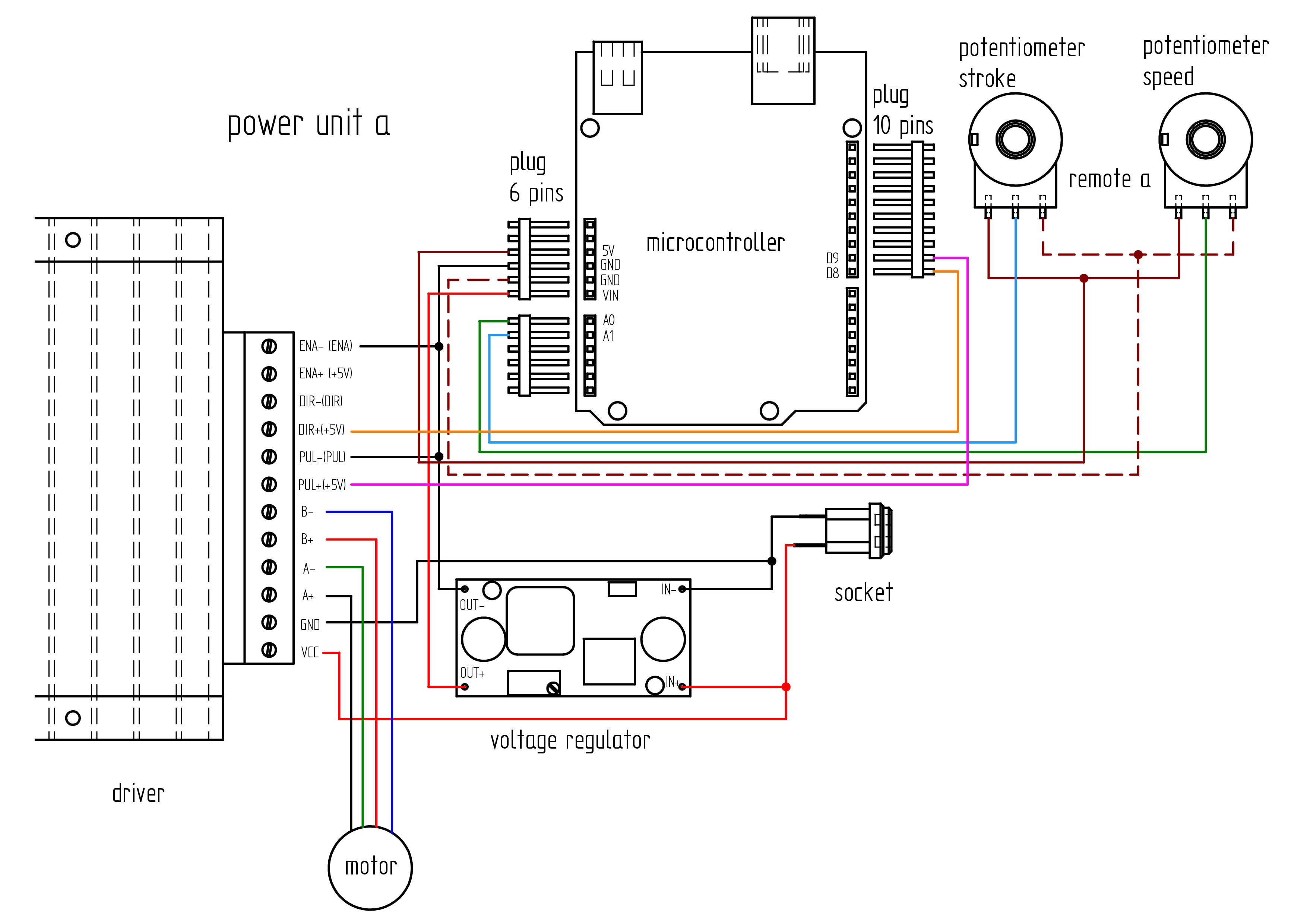
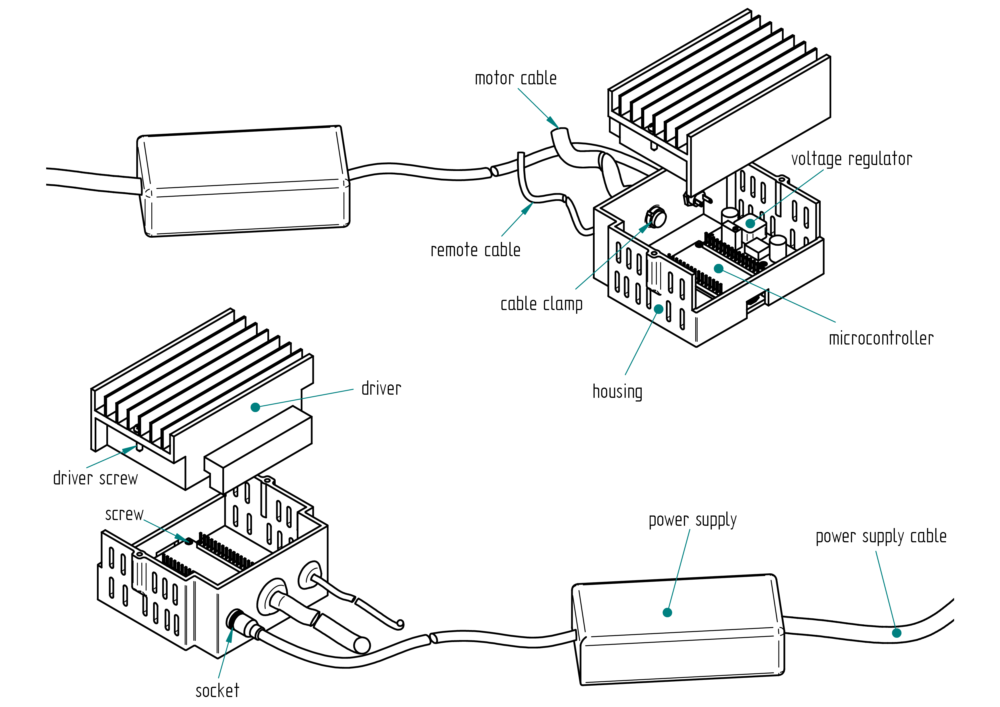
power unit a
This chapter explains how to build the power unit a.
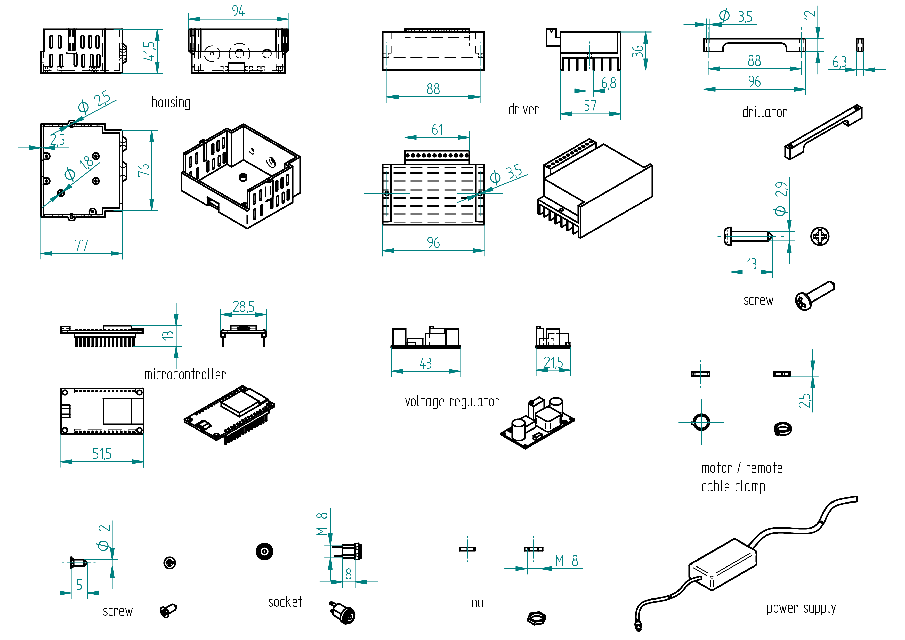
Parts list
| Qty | Part | Description | Material |
|---|---|---|---|
| 1 | housing | 3D printed | PLA |
| 1 | driver | TB6600 | - |
| 1 | microcontroller | Arduino Uno | - |
| 1 | plug 10 pins | delivered with Arduino Uno | - |
| 2 | plug 6 pins | delivered with Arduino Uno | - |
| 1 | voltage regulator | LM2596 | - |
| 1 | socket | 2.1/5.5 | - |
| 1 | nut | M8 | - |
| 6 | screw | M2 x 5 | brass |
| 2 | driver screw | 2.9 x 13 | stainless steel |
| 1 | motor cable clamp | 2.5 | nylon (cable tie) |
| 1 | remote cable clamp | 2.5 | nylon (cable tie) |
| 1 | power supply | 110-220V/24V 6A | - |
| 1 | power supply cable | plug depends on country 110 V or 220 V | - |
Drawing
.
Required Tools and Components
- 1x 3D printer ;
- 1x PLA ;
- 1x STL file housing ;
- 1x STL file drillator ;
- 1x file ;
- 1x 3.5 mm drill bit ;
- 1x chamfer mill ;
- 1x screw driver ;
- 1x drill press ;
- 1x driller ;
- 1x clamp.
Manufacturing Instructions
- 3D print the housing.
- 3D print the drillator.
- Clamp the drillator on the driver (see section Drawing).
- On a drill press, drill a 3.5 mm hole.
- File or chamfer the hole.
- Wire all connection (see section wiring).
- Tighten the motor cable clamp and the remote cable clamp.
- Assemble the voltage regulator, the microcontroller, the socket and close the housing with the driver.
Wiring
Wiring diagram
Parts list
| Qty | Part | Description | Material |
|---|---|---|---|
| 1 | power supply cable | plug depends on country 110 V or 220 V | - |
| 1 | motor cable | 4 poles 0.5mm2 length : 1 m ( If the motor is not supplied with its own cable, refer to the Appendix, for instructions on how to attach it.} | |
| 1 | wire | 0.5mm2 length : 1 m | cooper |
| 1 | wire | 0.75mm2 length : 0.50 m | cooper |
| 1 | RJ-45 cable | 8 cores length : 2.5 m | 3 mm diameter |
Required Tools and Components
- 1x wire cutter ;
- 1x wire stripper ;
- 1x terminal crimping tool ;
- 1x multimeter (voltmeter) ;
- 1x soldering iron ;
- 1x solder ;
- 1x gauge ;
- 1x screwdriver 0 ;
- 1x water pump pliers ;
- 1x electrical tape.
Wiring Instructions
The lengths and cross-sectional areas of the wires are listed in table , page .
Wire the components before installing them into the housing.
- Adjust the DIP switches on the driver to set the desired micro-step resolution and output current, referring to the driver's tables for the correct settings:
- Micro-step resolution: 1600 → S1 = OFF, S2 = ON, S3 = OFF
- Current: 3.5A (peak 4A) → S4 = OFF, S5 = OFF, S6 = OFF
- Solder four wires to the socket (see Terminals Connection and Wire Details in Table , page , and Wiring Diagram, page).
- Secure the socket to the housing.
- Connect the socket to the voltage regulator (IN- and IN+).
- Use a multimeter to adjust the output of the voltage regulator to 5V.
- Solder the four wires to the corresponding pins on the voltage regulator :
- Connect a wire from the socket to IN+ (input positive).
- Connect a wire from the socket to IN- (input negative).
- Connect a wire to OUT+ (output positive).
- Connect a wire to OUT- (output negative).
- If the motor does not already have a cable installed, solder four wires to the motor. See Appendix: Attach the motor cable , page , for instructions on how to attach it. (It is much easier if you can get a motor with the cable already wired.)
- Complete all wiring connections (see Terminals Connection and Wire Details in Table , page , and Wiring Diagram, page).
- Wire the remote-controller-a (if not yet done).
- Secure all components inside the housing.
- Upload the firmware (see Section ...).
Terminals Connections and Wires details
| Qty | Part | Description | Material |
|---|---|---|---|
| +_socket - IN+_voltage regulator | ... | 0.25 | |
| +_socket - VCC_driver | ... | 0.75 | |
| -_socket - IN-_voltage regulator | ... | 0.25 | |
| -_socket - GND_driver | ... | 0.25 | |
| OUT+_voltage regulator - VIN_plug 6 pins | ... | 0.25 | |
| OUT-_voltage regulator - ENA-_driver | ... | 0.25 | |
| ENA-_driver - GND_plug 6 pins | ... | 0.25 | |
| ENA-_driver - PUL-_driver | ... | 0.25 | |
| PUL+_driver - D9_plug 10 pins | ... | 0.25 | |
| DIR+_driver - D8_plug 10 pins | ... | 0.25 | |
| A+_driver - black_motor | ... | 0.75 | |
| A-_driver - green_motor | ... | 0.75 | |
| B+_driver - red_motor | ... | 0.75 | |
| B-_driver - blue_motor | ... | 0.75 | |
| A0_plug 6 pins - middle-pin_remote speed | 250 | 0.15 | |
| A1_plug 6 pins - middle-pin_remote stroke | 250 | 0.15 | |
| GND_plug 6 pins - left-pin_remote stroke and speed | 250 | 0.15 | |
| 5V_plug 6 pins - right-pin_remote stroke and speed | 250 | 0.15 |
Firmware
After all components have been installed and wired inside the housing, it is time to upload the firmware to the microcontroller.
m1
The firmware source code for the machine m1 is located in the
**firmware** directory. A portion of the firmware code
is shown below.
To upload the firmware, please follow the steps described in the Appendix.
// Comme le fait de lire la vitesse du potentiom\`etre prend relativement beaucoup de temps,
// cela r\'eduit la vitesse de pulsation de la pin 9. Pour parer \`a ceci le programme a \'et\'e adapt\'e
// pour lire la vitesse tous les 300 it\'erations \`a basse vitesse.
// Lorsque la vitesse du potentiom\`etre d\'epasse v\_max\_inv qui est la vitesse maximale \`a laquelle
// le moteur ne d\'ecroche pas \`a l'inversion du sens de rotation, des boucles d'acc\'el\'erations et de
// d\'ec\'el\'eration sont requises pour ne pas faire d\'ecrocher le moteur lors des inversions de sens de
// rotations. (avec ceci, il est possible de diminuer le d\'elai entre pulse \`a haute vitesse ce
// qui augmente la vitesse) Comme la vitesse est rapide la vitesse est alors lue apr\`es un cycle
// complet de va-et-vient. Pour simplifier, la course n'est lue qu'apr\`es un cycle complet de va-et-vient.
// Un autre point important est de lire la vitesse souvent \`a basse vitesse :
// par exemple si la vitesse est au mini et la course est grande, alors cela prendra une \'eternit\'e
// pour que le va-et-vient se termine jusqu'\`a la prochaine lecture de vitesse.
// L'acc\'el\'eration et la d\'ec\'el\'eration est lin\'eaire (apr\`es un cycle de pulse, le d\'elai est soustrait pour
// l'acc\'el\'eration ou additionn\'e de 1 pour la d\'ecc\'el\'eration).
#define step_pin 9          // Pin 9 connected to Steps pin on ST-M5045 ou ... c'est la pin du pulse
// (un pulse c'est un pas en mode full
// ou en mode 1600pas/rev : 8 pulses pour un pas avec un motor de 1.8deg
// ou 200pas/rev)
#define dir_pin 8           // Pin 8 connected to Direction pin
#define home_switch 12      // Pin 12 connected to Home Switch (MicroSwitch)
#define ref 0               // c'est le 0 ici l'inversion est faite en mode basse vitesse
// (sans acc'el'eration ni d'ec'el'eration)
//PARAMETRES MODIFIABLES**********************************
#define v_max 40            // C'est la vitesse maximale lue par le potentiom`etre de vitesse (d'elai en
// microseconde entre deux pulses) 30 50 45 55 65 70 65 Valeur original 50.
#define v_min 1200          // C'est la vitesse minimum lue par le potentiom`etre de vitesse (d'elai en
// microseconde entre deux pulses)
#define v_max_inv 200       // C'est la vitesse maximale `a laquelle le moteur ne d'ecroche pas 200 280
// Valeur pr'ec'edente=200 `a l'inversion de sens de rotation (200 pour Gecko
// et 200 pour 1600pas/rev?). En dessous de cette vitesse, l'acc'el'eration
// et la d'ec'el'eration ne sont pas requises. C'est pourquoi la course peut ^etre
// plus petite car il n'y a pas besoin de distance de freinage. `A cette petite
// course le va-et-vient est tellement rapide que  ca vibre. On retrouve ici
// le mode vibro.
#define course_max 2968     // C'est la course maximale lue par le potentiom`etre de course 2150 2125
// 2100 2080 origine 2320 2500 Cette valeur d'epende de la longueur de la
// machine.
#define marge 30            // C'est la marge ou d'ecalage de la r'ef'erence par rapport `a la position du
// bras `a la mise sous tension de la machine en principe en but'ee du c^ot'e
// vert ou c^ot'e rouge. Ceci assure que la partie mobile ne vienne cogn'er
// sur l'un des c^ot'es. Valeur originale = 50.
//****************************************************************************************************
int course_min = 296;       // C'est la course minimum lue par le potentiom`etre de course. Qui corresond
// `a la course minimum pour l'acc'el'eration et la d'ec'el'eration `a haute vitesse.
// (vitesse `a laquelle la distance de freinage/acc'el'eration est requise).
// Soit course_min > 2*(v_max_inv - v_max) = distance max de freinage ou
// d'acc'el'eration.
m2
The firmware source code for the machine m2 is located in the
**firmware** directory. A portion of the firmware code
is shown below.
To upload the firmware, please follow the steps described in the Appendix.
// Comme le fait de lire la vitesse du potentiom\`etre prend relativement beaucoup de temps,
// cela r\'eduit la vitesse de pulsation de la pin 9. Pour parer \`a ceci le programme a \'et\'e adapt\'e
// pour lire la vitesse tous les 300 it\'erations \`a basse vitesse.
// Lorsque la vitesse du potentiom\`etre d\'epasse v\_max\_inv qui est la vitesse maximale \`a laquelle
// le moteur ne d\'ecroche pas \`a l'inversion du sens de rotation, des boucles d'acc\'el\'erations et de
// d\'ec\'el\'eration sont requises pour ne pas faire d\'ecrocher le moteur lors des inversions de sens de
// rotations. (avec ceci, il est possible de diminuer le d\'elai entre pulse \`a haute vitesse ce
// qui augmente la vitesse) Comme la vitesse est rapide la vitesse est alors lue apr\`es un cycle
// complet de va-et-vient. Pour simplifier, la course n'est lue qu'apr\`es un cycle complet de va-et-vient.
// Un autre point important est de lire la vitesse souvent \`a basse vitesse :
// par exemple si la vitesse est au mini et la course est grande, alors cela prendra une \'eternit\'e
// pour que le va-et-vient se termine jusqu'\`a la prochaine lecture de vitesse.
// L'acc\'el\'eration et la d\'ec\'el\'eration est lin\'eaire (apr\`es un cycle de pulse, le d\'elai est soustrait pour
// l'acc\'el\'eration ou additionn\'e de 1 pour la d\'ecc\'el\'eration).
#define step_pin 9          // Pin 9 connected to Steps pin on ST-M5045 ou ... c'est la pin du pulse
// (un pulse c'est un pas en mode full
// ou en mode 1600pas/rev : 8 pulses pour un pas avec un motor de 1.8deg
// ou 200pas/rev)
#define dir_pin 8           // Pin 8 connected to Direction pin
#define home_switch 12      // Pin 12 connected to Home Switch (MicroSwitch)
#define ref 0               // c'est le 0 ici l'inversion est faite en mode basse vitesse
// (sans acc'el'eration ni d'ec'el'eration)
//PARAMETRES MODIFIABLES**********************************
#define v_max 40            // C'est la vitesse maximale lue par le potentiom`etre de vitesse (d'elai en
// microseconde entre deux pulses) 30 50 45 55 65 70 65 Valeur original 50.
#define v_min 1200          // C'est la vitesse minimum lue par le potentiom`etre de vitesse (d'elai en
// microseconde entre deux pulses)
#define v_max_inv 200       // C'est la vitesse maximale `a laquelle le moteur ne d'ecroche pas 200 280
// Valeur pr'ec'edente=200 `a l'inversion de sens de rotation (200 pour Gecko
// et 200 pour 1600pas/rev?). En dessous de cette vitesse, l'acc'el'eration
// et la d'ec'el'eration ne sont pas requises. C'est pourquoi la course peut ^etre
// plus petite car il n'y a pas besoin de distance de freinage. `A cette petite
// course le va-et-vient est tellement rapide que  ca vibre. On retrouve ici
// le mode vibro.
#define course_max 2968     // C'est la course maximale lue par le potentiom`etre de course 2150 2125
// 2100 2080 origine 2320 2500 Cette valeur d'epende de la longueur de la
// machine.
#define marge 30            // C'est la marge ou d'ecalage de la r'ef'erence par rapport `a la position du
// bras `a la mise sous tension de la machine en principe en but'ee du c^ot'e
// vert ou c^ot'e rouge. Ceci assure que la partie mobile ne vienne cogn'er
// sur l'un des c^ot'es. Valeur originale = 50.
//****************************************************************************************************
int course_min = 296;       // C'est la course minimum lue par le potentiom`etre de course. Qui corresond
// `a la course minimum pour l'acc'el'eration et la d'ec'el'eration `a haute vitesse.
// (vitesse `a laquelle la distance de freinage/acc'el'eration est requise).
// Soit course_min > 2*(v_max_inv - v_max) = distance max de freinage ou
// d'acc'el'eration.
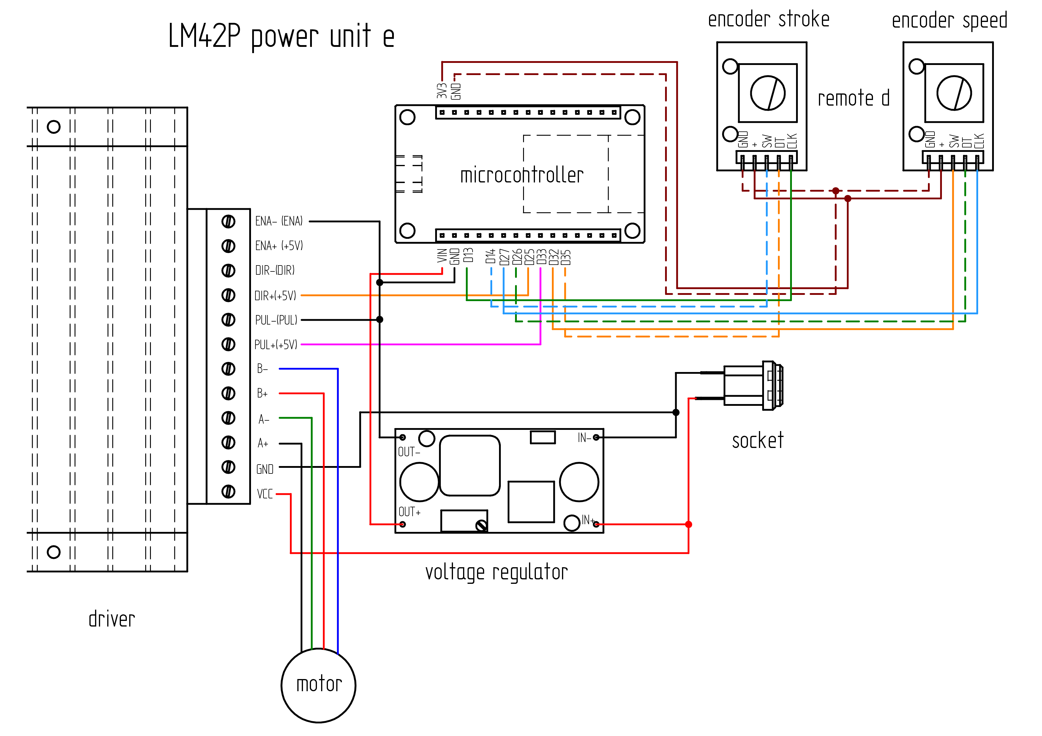
power unit e

This chapter explains how to build the power unit e.
Parts list
| Qty | Part | Description | Material |
|---|---|---|---|
| 1 | housing | 3D printed | PLA |
| 1 | driver | TB6600 | - |
| 1 | microcontroller | ESP32 30 pins | - |
| 1 | voltage regulator | LM2596 | - |
| 1 | socket | 2.1/5.5 | - |
| 1 | nut | M8 | - |
| 6 | screw | M2 x 5 | brass |
| 2 | driver screw | 2.9 x 13 | stainless steel |
| 1 | motor cable clamp | 2.5 | nylon (cable tie) |
| 1 | remote cable clamp | 2.5 | nylon (cable tie) |
| 1 | power supply | 110-220V/24V 6A | - |
| 1 | power supply cable | plug depends on country 110 V or 220 V | - |
Drawing
.
Required Tools and Components
- 1x 3D printer ;
- 1x PLA ;
- 1x STL file housing ;
- 1x STL file drillator ;
- 1x file ;
- 1x 3.5 mm drill bit ;
- 1x chamfer mill ;
- 1x screw driver ;
- 1x drill press ;
- 1x driller ;
- 1x clamp.
Manufacturing Instructions
- 3D print the housing.
- 3D print the drillator.
- Clamp the drillator on the driver (see section drawing).
- On a drill press, drill a 3.5 mm hole.
- File or chamfer the hole.
- Wire all connection (see section Wiring).
- Tighten the motor cable clamp and the remote cable clamp.
- Assemble the voltage regulator, the microcontroller, the socket and close the housing with the driver.
Wiring
Wiring diagram
Parts list
| Qty | Part | Description | Material |
|---|---|---|---|
| 1 | motor cable | 4 poles 0.5mm2 length : 1 m ( If the motor is not supplied with its own cable, refer to the Appendix, for instructions on how to attach it.} | |
| 1 | wire | 0.5mm2 length : 1 m | cooper |
| 1 | wire | 0.75mm2 length : 0.50 m | cooper |
| 1 | RJ-45 cable | 8 cores length : 2.5 m | 3 mm diameter |
Required Tools and Components
- 1x wire cutter ;
- 1x wire stripper ;
- 1x terminal crimping tool ;
- 1x multimeter (voltmeter) ;
- 1x soldering iron ;
- 1x solder ;
- 1x gauge ;
- 1x screwdriver 0 ;
- 1x water pump pliers ;
- 1x electrical tape.
Wiring Instructions
The lengths and cross-sectional areas of the wires are listed in table , page .
Wire the components before installing them into the housing.
- Adjust the DIP switches on the driver to set the desired micro-step resolution and output current, referring to the driver's tables for the correct settings:
- Micro-step resolution: 1600 → S1 = OFF, S2 = ON, S3 = OFF
- Current: 3.5A (peak 4A) → S4 = OFF, S5 = OFF, S6 = OFF
- Solder four wires to the socket (see Terminals Connection and Wire Details in Table , page , and Wiring Diagram, page).
- Secure the socket to the housing.
- Connect the socket to the voltage regulator (IN- and IN+).
- Use a multimeter to adjust the output of the voltage regulator to 5V.
- Solder the four wires to the corresponding pins on the voltage regulator :
- Connect a wire from the socket to IN+ (input positive).
- Connect a wire from the socket to IN- (input negative).
- Connect a wire to OUT+ (output positive).
- Connect a wire to OUT- (output negative).
- If the motor does not already have a cable installed, solder four wires to the motor. See Appendix: Attach the motor cable , page , for instructions on how to attach it. (It is much easier if you can get a motor with the cable already wired.)
- Complete all wiring connections (see Terminals Connection and Wire Details in Table , page , and Wiring Diagram, page).
- Wire the remote-controller-d (cut the RJ-45 plug and use only the cable) (if not yet done).
- Secure all components inside the housing.
- Upload the firmware (see Section Firmware).
Terminals Connections and Wires details
| Qty | Part | Description | Material |
|---|---|---|---|
| +_socket - IN+_voltage regulator | ... | 0.25 | |
| +_socket - VCC_driver | ... | 0.75 | |
| -_socket - IN-_voltage regulator | ... | 0.25 | |
| -_socket - GND_driver | ... | 0.25 | |
| OUT+_voltage regulator - VIN_microcontroller | ... | 0.25 | |
| OUT-_voltage regulator - ENA-_driver | ... | 0.25 | |
| ENA-_driver - GND_microcontroller | ... | 0.25 | |
| ENA-_driver - PUL-_driver | ... | 0.25 | |
| PUL+_driver - D33_microcontroller | ... | 0.25 | |
| DIR+_driver - D25_microcontroller | ... | 0.25 | |
| A+_driver - black_motor | ... | 0.75 | |
| A-_driver - green_motor | ... | 0.75 | |
| B+_driver - red_motor | ... | 0.75 | |
| B-_driver - blue_motor | ... | 0.75 | |
| D13_microcontroller - CLK_encoder stroke | 250 | 0.15 | |
| D14_microcontroller - SW_encoder stroke | 250 | 0.15 | |
| D27_microcontroller - CLK_encoder speed | 250 | 0.15 | |
| D26_microcontroller - DT_encoder speed | 250 | 0.15 | |
| D32_microcontroller - SW_encoder speed | 250 | 0.15 | |
| D35_microcontroller - DT_encoder stroke | 250 | 0.15 | |
| 3V3_microcontroller - +_encoder stroke and speed | 250 | 0.15 | |
| GND_microcontroller - GND_encoder stroke and speed | 250 | 0.15 |
Firmware
After all components have been installed and wired inside the housing, it is time to upload the firmware to the microcontroller.
m1
The firmware source for the machine m1 code is located in the
**firmware** directory. A portion of the firmware code
is shown below.
To upload the firmware, please follow the steps described in the Appendix.
//speed rotary encoder
#define ROTARY_ENCODER_A_PIN 27 //CLK
#define ROTARY_ENCODER_B_PIN 26 //DT
#define ROTARY_ENCODER_BUTTON_PIN 32 //SW
#define ROTARY_ENCODER_STEPS 4
#define ROTARY_ENCODER_ACCELERATION 2000 //30000 3000
AiEsp32RotaryEncoder rotaryEncoder = AiEsp32RotaryEncoder(ROTARY_ENCODER_A_PIN, ROTARY_ENCODER_B_PIN, ROTARY_ENCODER_BUTTON_PIN, -1, ROTARY_ENCODER_STEPS);
// stroke rotary encoder
#define ROTARY_ENCODER2_A_PIN 13 //CLK
#define ROTARY_ENCODER2_B_PIN 35 //DT
#define ROTARY_ENCODER2_BUTTON_PIN 14 //SW
#define ROTARY_ENCODER2_STEPS 4
#define ROTARY_ENCODER2_ACCELERATION 7000
AiEsp32RotaryEncoder rotaryEncoder2 = AiEsp32RotaryEncoder(ROTARY_ENCODER2_A_PIN, ROTARY_ENCODER2_B_PIN, ROTARY_ENCODER2_BUTTON_PIN, -1, ROTARY_ENCODER2_STEPS);
void IRAM_ATTR readEncoderISR()
{
rotaryEncoder.readEncoder_ISR();
rotaryEncoder2.readEncoder_ISR();
}
// IO pin assignments
const int MOTOR_STEP_PIN = 33;
const int MOTOR_DIRECTION_PIN = 25;
m2
The firmware source code for the machine m2 is located in the
**firmware** directory. A portion of the firmware code
is shown below.
To upload the firmware, please follow the steps described in the Appendix.
//speed rotary encoder
#define ROTARY_ENCODER_A_PIN 27 //CLK
#define ROTARY_ENCODER_B_PIN 26 //DT
#define ROTARY_ENCODER_BUTTON_PIN 32 //SW
#define ROTARY_ENCODER_STEPS 4
#define ROTARY_ENCODER_ACCELERATION 2000 //30000 3000
AiEsp32RotaryEncoder rotaryEncoder = AiEsp32RotaryEncoder(ROTARY_ENCODER_A_PIN, ROTARY_ENCODER_B_PIN, ROTARY_ENCODER_BUTTON_PIN, -1, ROTARY_ENCODER_STEPS);
// stroke rotary encoder
#define ROTARY_ENCODER2_A_PIN 13 //CLK
#define ROTARY_ENCODER2_B_PIN 35 //DT
#define ROTARY_ENCODER2_BUTTON_PIN 14 //SW
#define ROTARY_ENCODER2_STEPS 4
#define ROTARY_ENCODER2_ACCELERATION 7000
AiEsp32RotaryEncoder rotaryEncoder2 = AiEsp32RotaryEncoder(ROTARY_ENCODER2_A_PIN, ROTARY_ENCODER2_B_PIN, ROTARY_ENCODER2_BUTTON_PIN, -1, ROTARY_ENCODER2_STEPS);
void IRAM_ATTR readEncoderISR()
{
rotaryEncoder.readEncoder_ISR();
rotaryEncoder2.readEncoder_ISR();
}
// IO pin assignments
const int MOTOR_STEP_PIN = 33;
const int MOTOR_DIRECTION_PIN = 25;
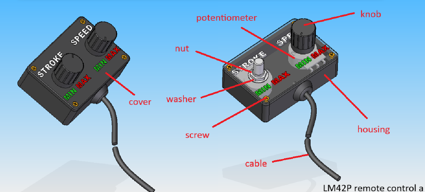
remote control d
This is the digital remote control named remote control d (the letter d stands for digital). It can be used either with the power unit p or the power unit e.
Note that the power unit p uses a cable with an RJ-45 plug, while the power unit e does not, as its plug has been removed (cut off).

Parts list
| Qty | Part | Description | Material |
|---|---|---|---|
| 1 | housing | 3D printed | PLA |
| 1 | cover | 3D printed | PLA |
| 2 | encoder | with switch | |
| 2 | knob | 14 x 16.5 mm | aluminium |
| 1 | cable | 3 x 2500 mm LAN RJ45 | - |
| 1 | cable clamp | 2.5 mm | nylon |
| 10 | screw | 2 x 10 mm | brass |
| 1 | stroke inscription | molded into cavity | pigmented white epoxy |
| 1 | speed inscription | molded into cavity | pigmented white epoxy |
| 1 | min inscription | molded into cavity | pigmented green epoxy |
| 1 | max inscription | molded into cavity | pigmented red epoxy |
Drawing
Required Tools and Components
- 1x 3D printer ;
- 1x PLA ;
- 1x STL file housing ;
- 1x file ;
- 1x chamfer mill ;
- 1x screw driver ;
- ..g resine ;
- ..g hardener ;
- ..g pigmented white epoxy ;
- ..g pigmented green epoxy ;
- ..g pigmented red epoxy ;
- water sandpaper 80 ;
- water sandpaper 150 ;
- water sandpaper 220 ;
- water sandpaper 400.
Manufacturing Instructions
- 3D print the housing.
- 3D print the cover.
- Prepare :
- pigmented white epoxy;
- pigmented green epoxy;
- pigmented red epoxy.
- Fill the cavities with the corresponding epoxy colors for the inscriptions.
- Allow to cure for 24 hours.
- Wet-sand the top of the cover up to 400-grit sandpaper.
- Install both potentiometers.
- Wire all connections (see Section , page ).
- Tighten the remote cable clamp.
- Close the housing using the cover.
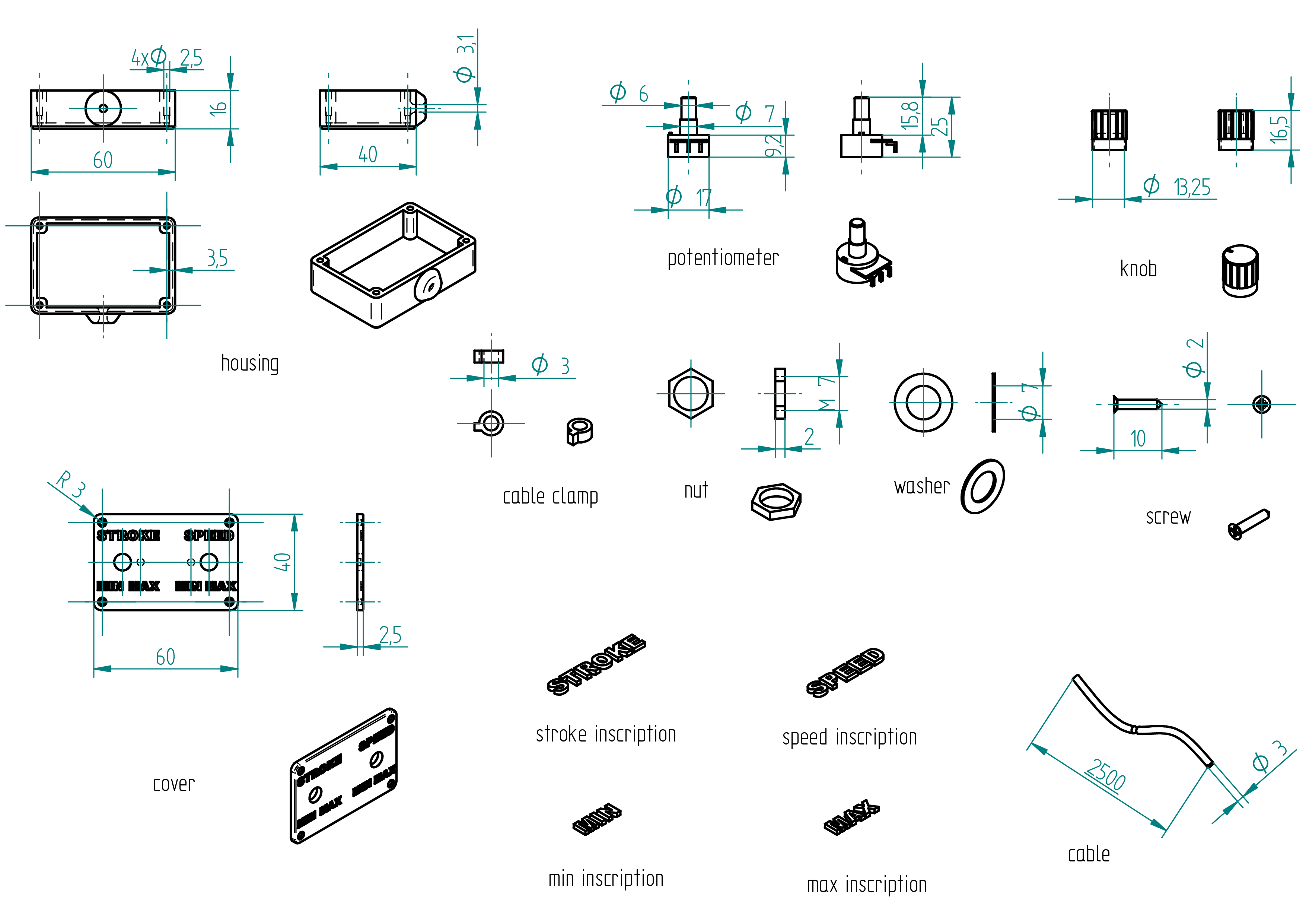
remote control a
This is the digital remote control (the letter a stands for analogic). It is used with the power unit a (It can be use also with power unit e or p) but not showed in this documentation.
Note that the power unit a uses a remote cable without an RJ-45 plug, so just cut it off.
Parts list
| Qty | Part | Description | Material |
|---|---|---|---|
| 1 | housing | 3D printed | PLA |
| 1 | cover | 3D printed | PLA |
| 2 | encoder | with switch | |
| 2 | knob | 14 x 16.5 mm | aluminium |
| 1 | cable | 3 x 2500 mm LAN RJ45 (without plug) | - |
| 1 | cable clamp | 2.5 mm | nylon |
| 4 | screw | 2 x 10 mm | brass |
| 1 | stroke inscription | molded into cavity | pigmented white epoxy |
| 1 | speed inscription | molded into cavity | pigmented white epoxy |
| 1 | min inscription | molded into cavity | pigmented green epoxy |
| 1 | max inscription | molded into cavity | pigmented red epoxy |
Drawing
Required Tools and Components
- 1x 3D printer ;
- 1x PLA ;
- 1x STL file housing ;
- 1x file ;
- 1x chamfer mill ;
- 1x screw driver ;
- ..g resine ;
- ..g hardener ;
- ..g pigmented white epoxy ;
- ..g pigmented green epoxy ;
- ..g pigmented red epoxy ;
- Wet sandpaper, grit 80;
- Wet sandpaper, grit 150;
- Wet sandpaper, grit 220;
- Wet sandpaper, grit 400.
Manufacturing Instructions
- 3D print the housing.
- 3D print the cover.
- Prepare :
- pigmented white epoxy;
- pigmented green epoxy;
- pigmented red epoxy.
- Fill the cavities with the corresponding epoxy colors for the inscriptions.
- Allow to cure for 24 hours.
- Wet-sand the top of the cover up to 400-grit sandpaper.
- Install both potentiometers.
- Wire all connections (see Section , page ).
- Tighten the remote cable clamp.
- Close the housing using the cover.
Shaped Tools
In this chapter, I introduce the tools required to build all the machines described in this building plan. I present the perpendiculator—a tool used to make the ends or faces of a tube, or any part, perfectly perpendicular.
perpendiculator
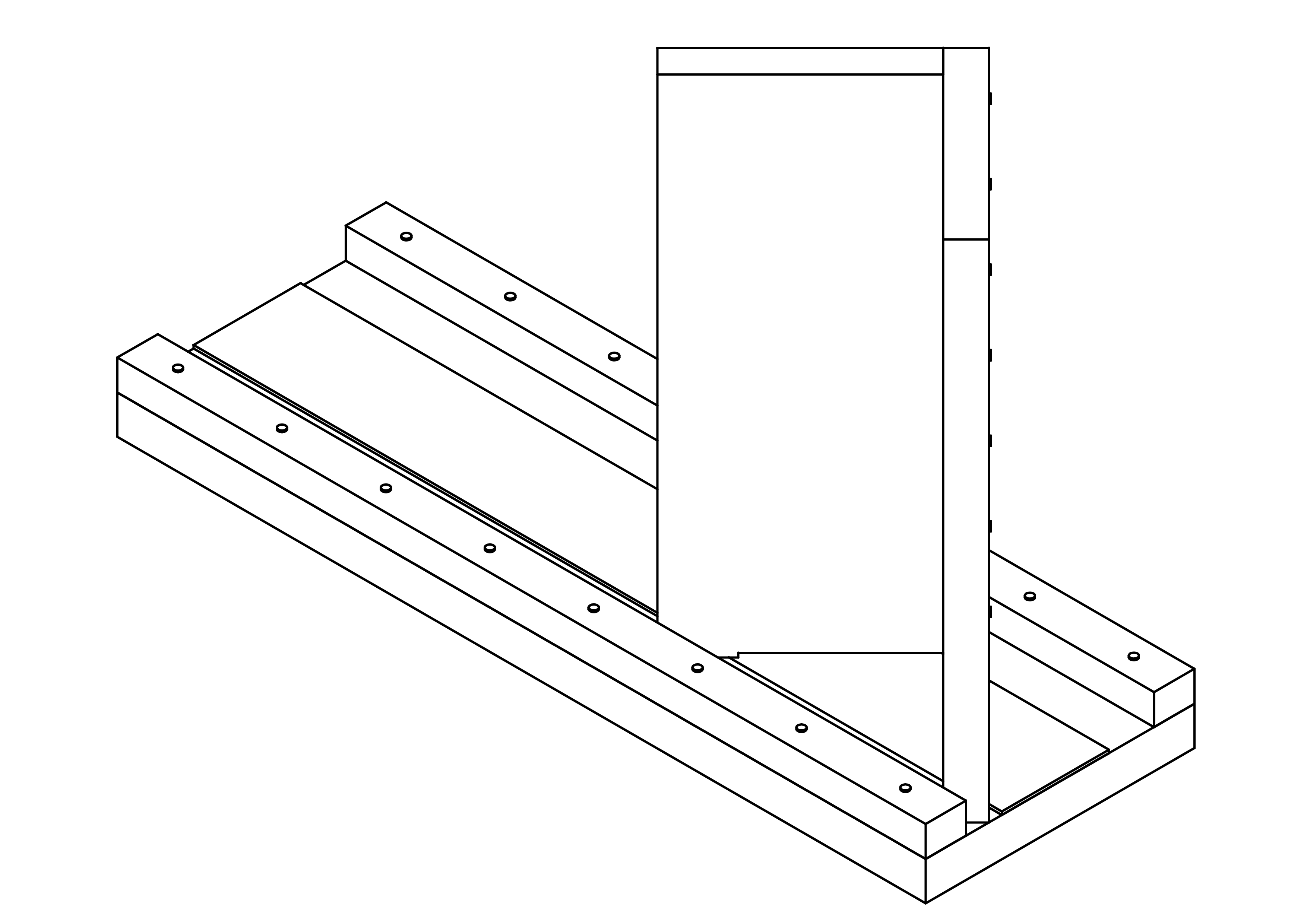
In this section I introduce how to build the perpendiculator. This tool has two assemblies the plane and the slider. They have both a paragraph in which all details are explained. In the paragraph Assemblies the whole tool are assembled with the sub-assemblies plane and slider. And in the paragraph Normalized parts are showed all the normalized parts which are used for the plane and the slider (for example wooden glue, nails).
Roadmap
In this section we can find the roadmap to build the perpendiculator. It's not necessary to follow straight all these points after another, but I think it's the most logical to do it like this :
- prepare all stuff in the Parts-list with the tools showed in the Tools-list ;
- assemble the slider ;
- assemble the base.
Parts list
In this section we can find the whole list of parts that the perpendiculator needs, like :
- 1x base size 133x400x19 in MDF ;
- 1x rectangular-wooden-list size 15x20x1000 in beech
for :
- 2x guide.
- 1x sandpaper ;
- 1x face-1 size 100x250x16 in MDF ;
- 1x face-2 size 116x250x16 in MDF ;
- 1x nails (box) size 1.4x30 ;
- 1x wooden glue ;
- 1x amidon glue.
Tools list
In this section we can find the list of tools that we need to build the perpendiculator, like :
- 1x hammer ;
- 1x drill press ;
- 1x 1.4mm diameter drill ;
- 2x clamps ;
- 1x ruler ;
- sandpager.
Shaped parts
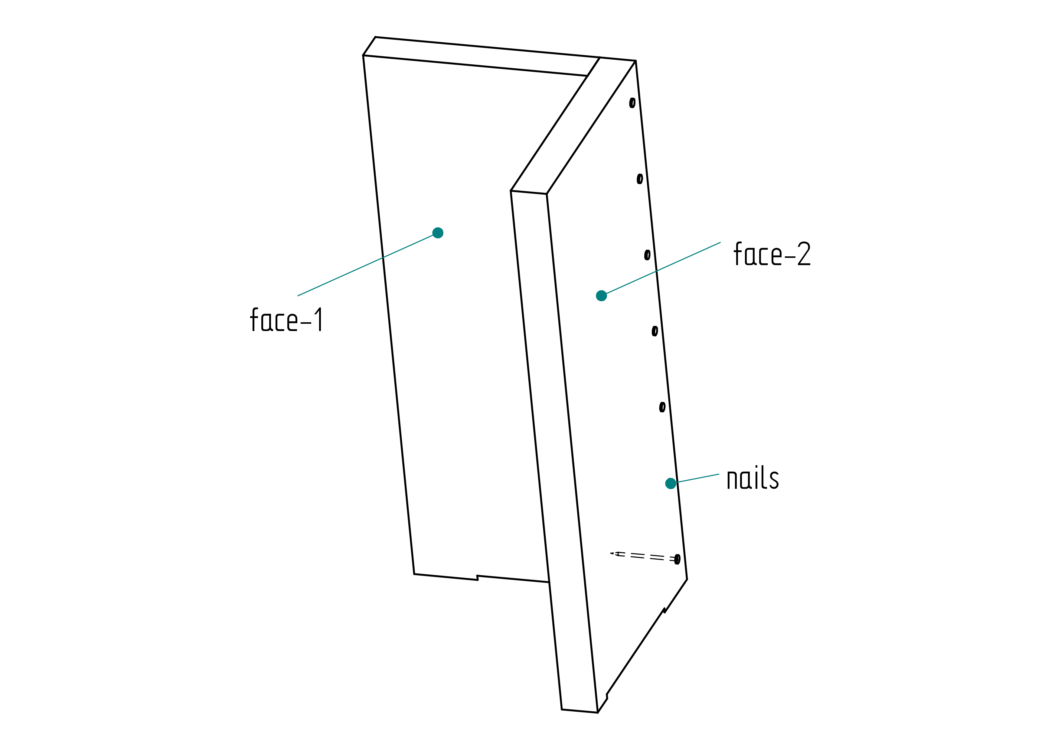
In this paragraph we can find all the shaped parts of the perpendiculator, like :
- base ;
- guide ;
- sandpaper ;
- face-1 ;
- face-2.
base
Here is shown the information for the shaped part base.
- order in a carpentry.
That's all for this part.
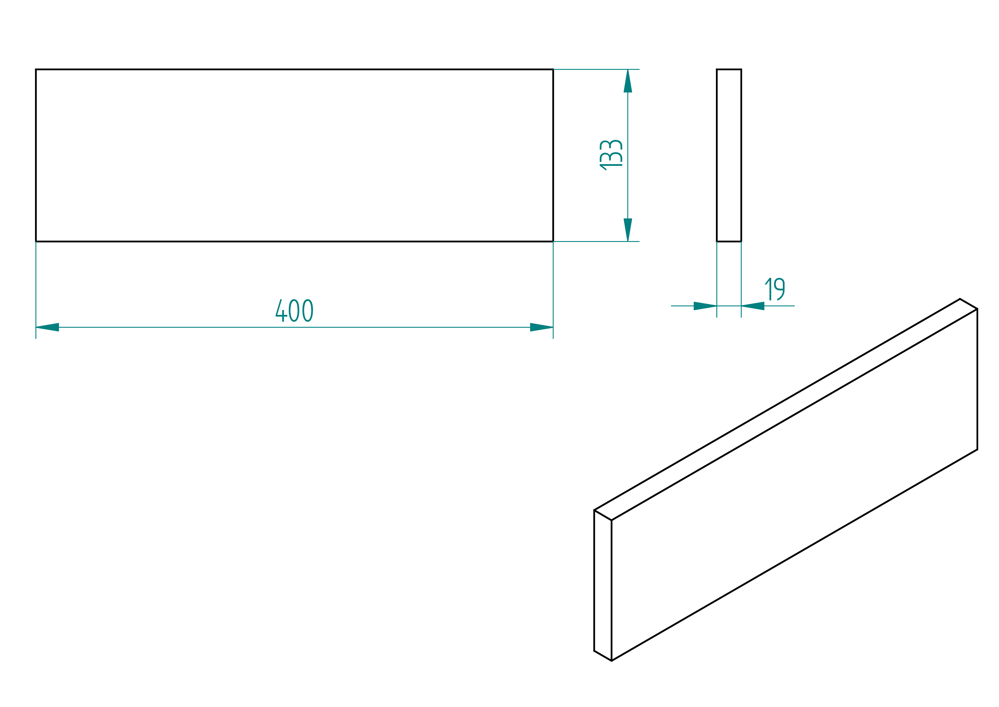
- quantity: 1 ;
- material: MDF ;
- provider: carpentry ;
- price: ?.
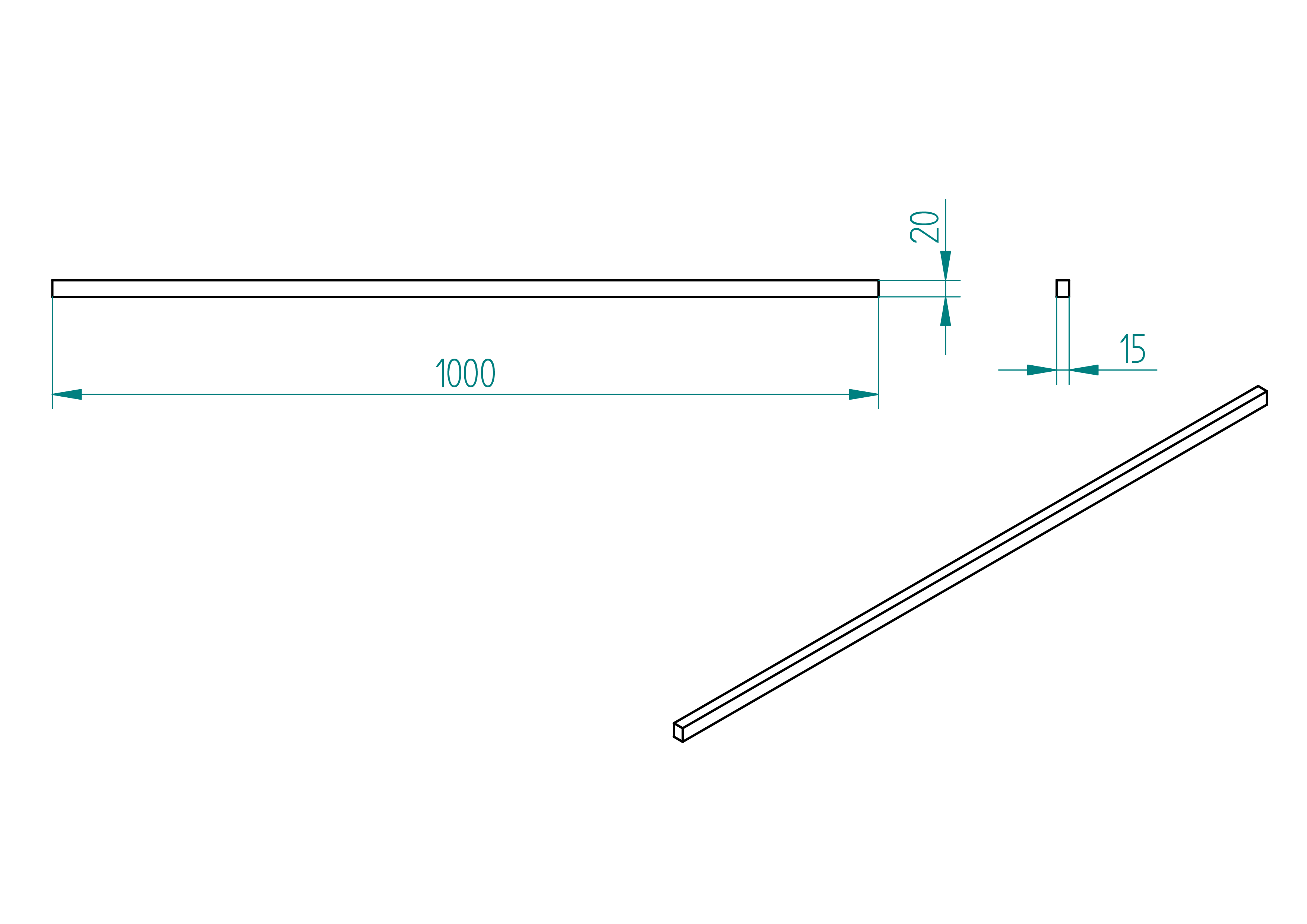
guide
This section shows how to build the guide of the perpendiculator tool.
- order the rectangular-wooden-list see section , ;
- ask at the carpentry to cut it at the good length (see the length on the figure , page ) ;
- drill the holes with diameter 1.4mm (for the positions).
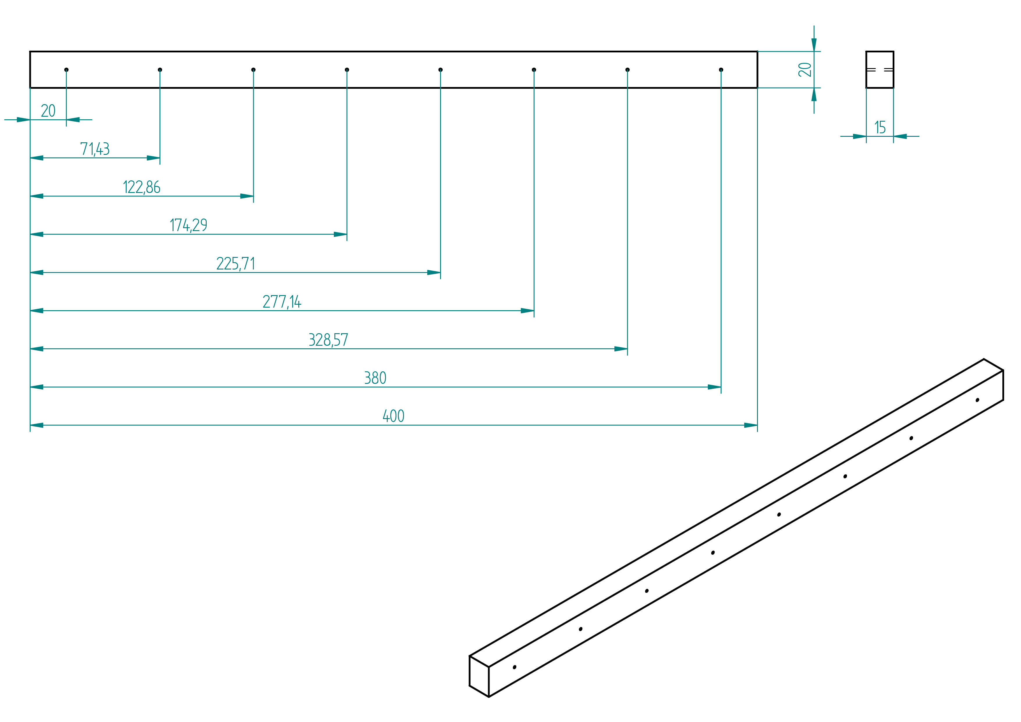
- quantity: 2 ;
- material: beech ;
- provider: ironmongery ;
- price: ? .
sandpaper
- quantity: 1 ;
- material: emery granularity : 80 ;
- provider: ironmongery ;
- price: ?.
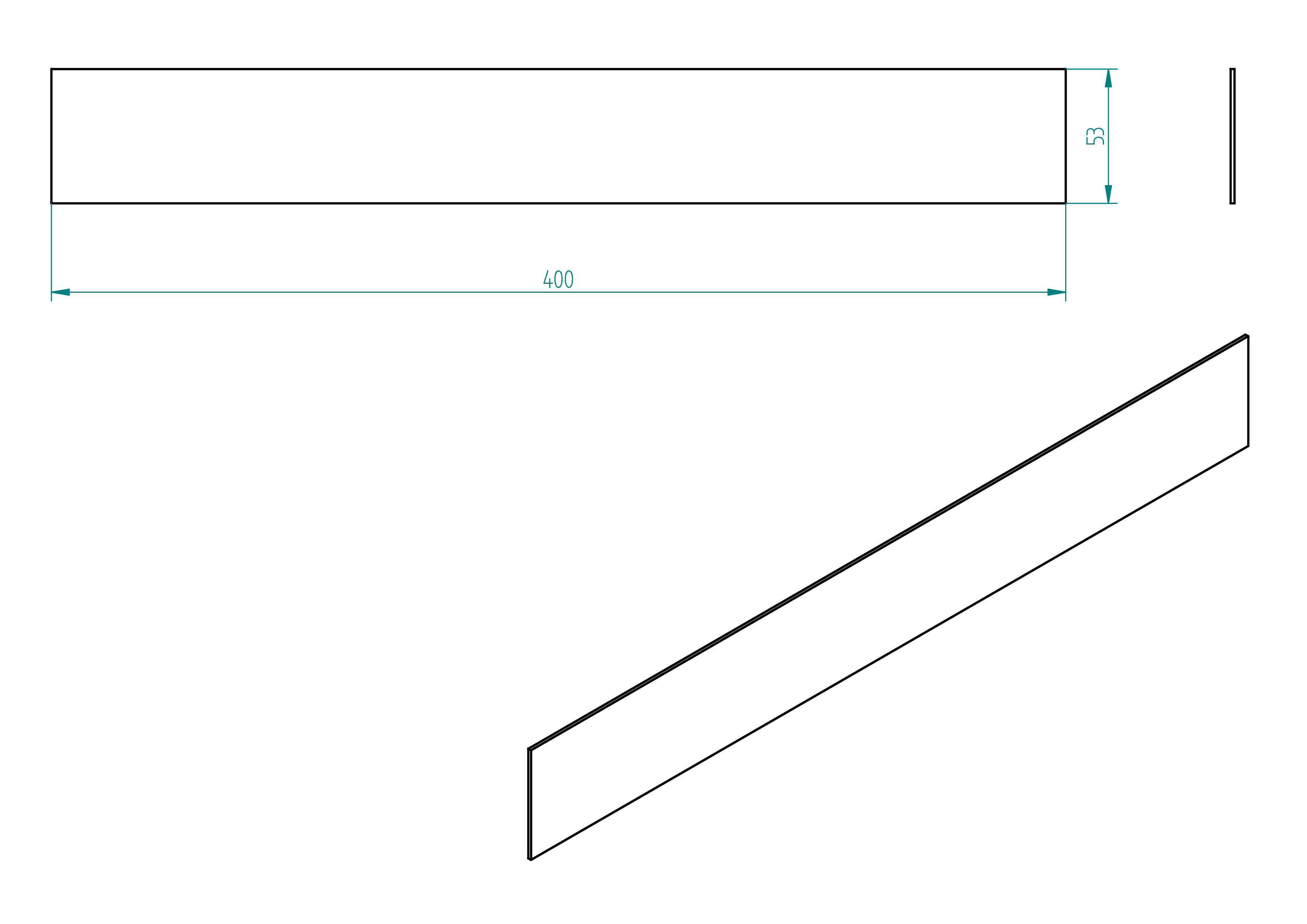
face-1
- order the part in a joinery for dimensions.
This is how the face-1 looks at the end.
- quantity: 1 ;
- material: MDF ;
- provider: joinery ;
- price: ?.
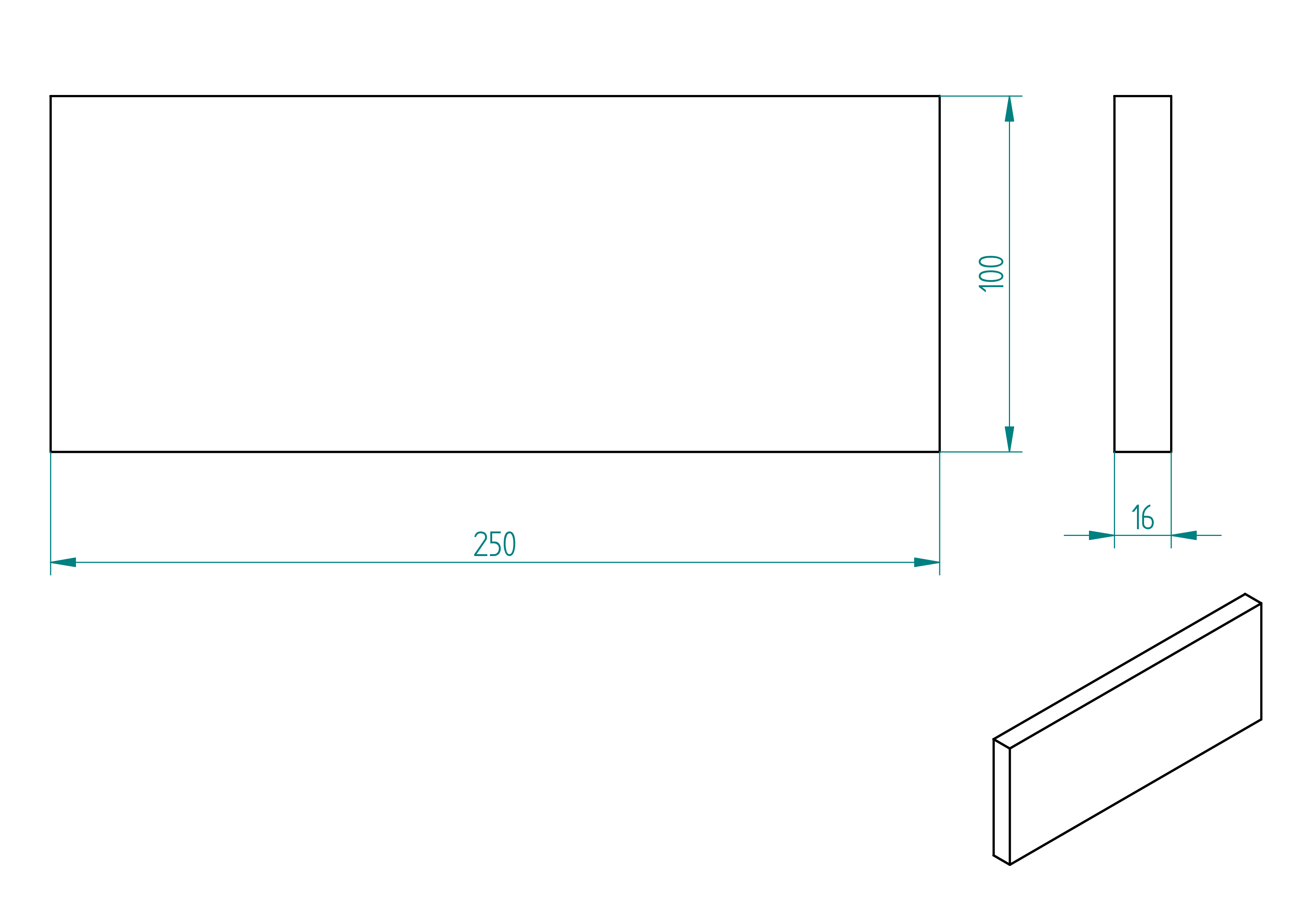
face-2
- order the part in a joinery for dimensions ;
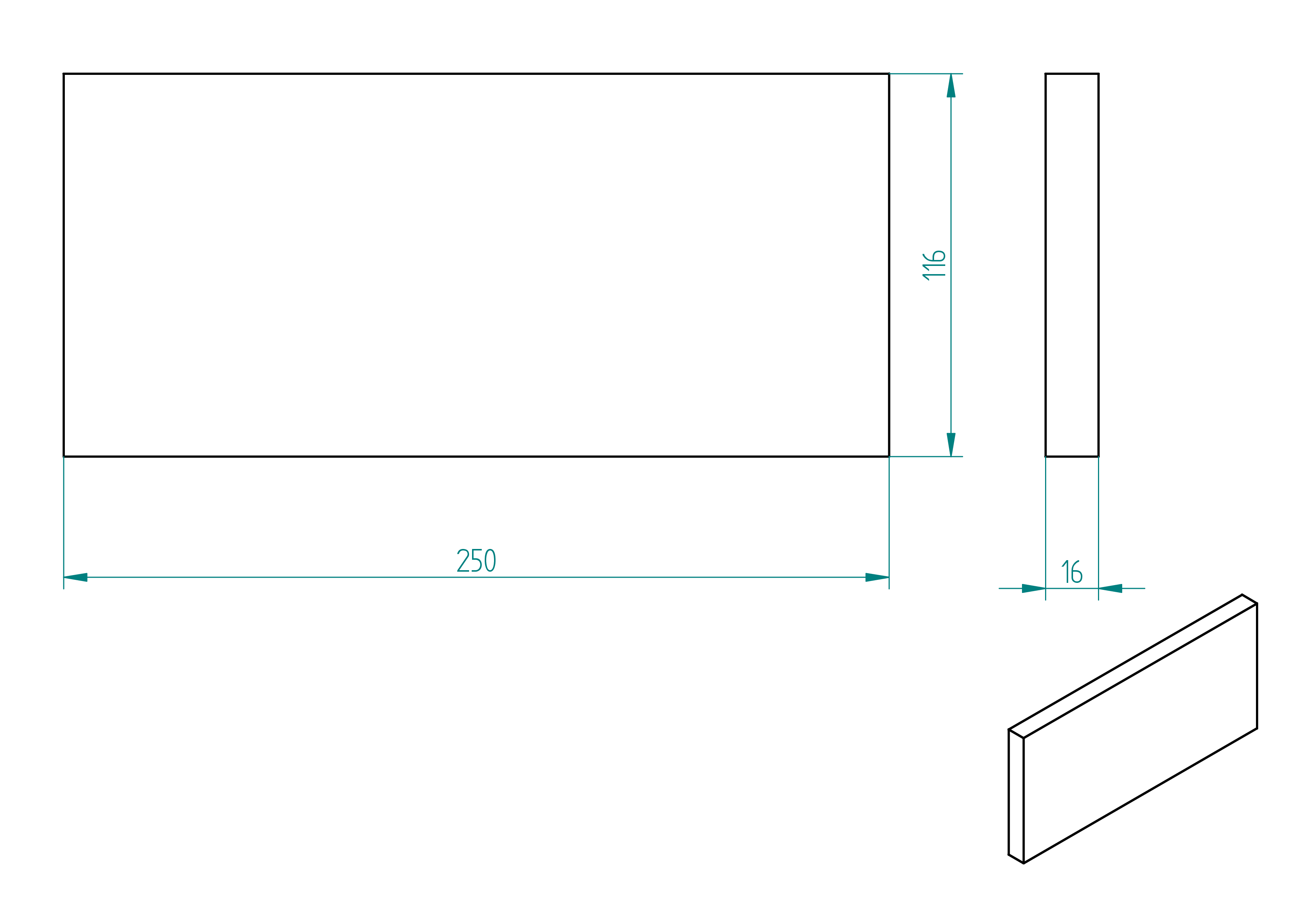
- drill the holes for dimension of the hole and positions .
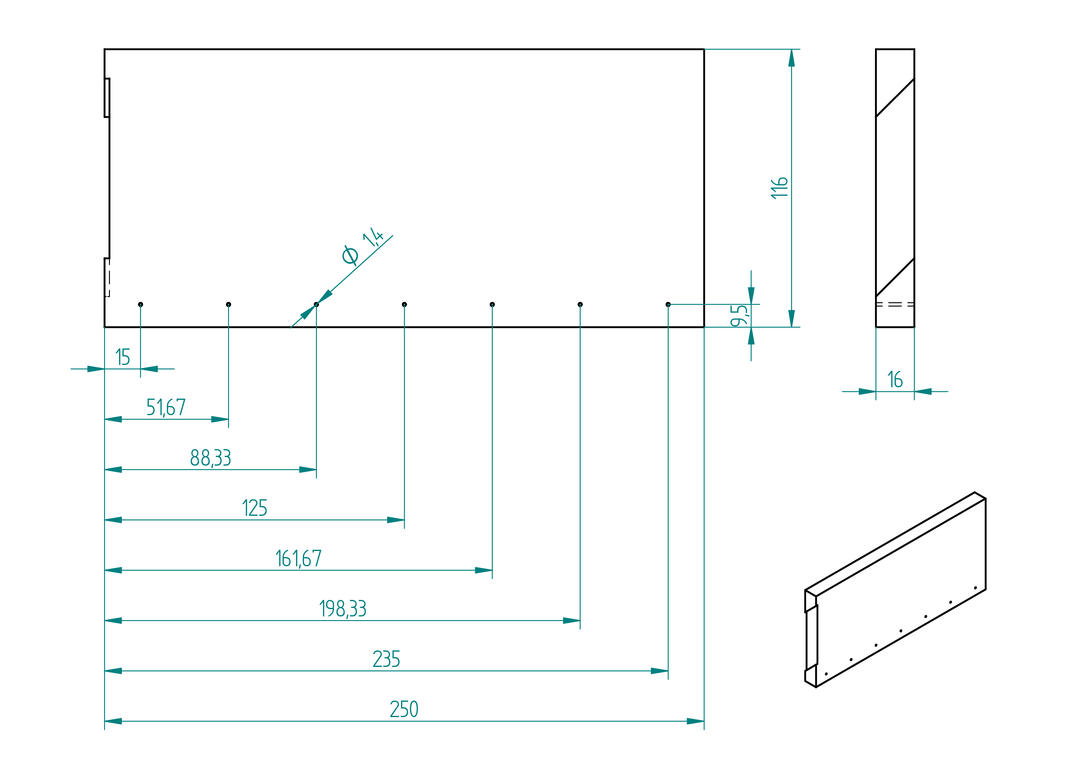
- quantity: 1 ;
- material: MDF ;
- provider: ironmongery ;
- price: ?.
Normalized parts
In this paragraph the normalized parts of the perpendiculator are showed. Like :
- sandpaper ;
- nails.
rectangular-wooden-list
Here are some information of the rectangular-wooden-list which are used to build the perpendiculator.
- quantity: 1 ;
- material: beech ;
- provider: ironmongery ;
- price: 5.20frs.
sandpaper
Here are some information of the sandpaper which are used for the perpendiculator.
- Size: ? ;
- Provider: any ironmongery ;
- Price: ?
nails
Here are some information of the nails which are used to build the perpendiculator.
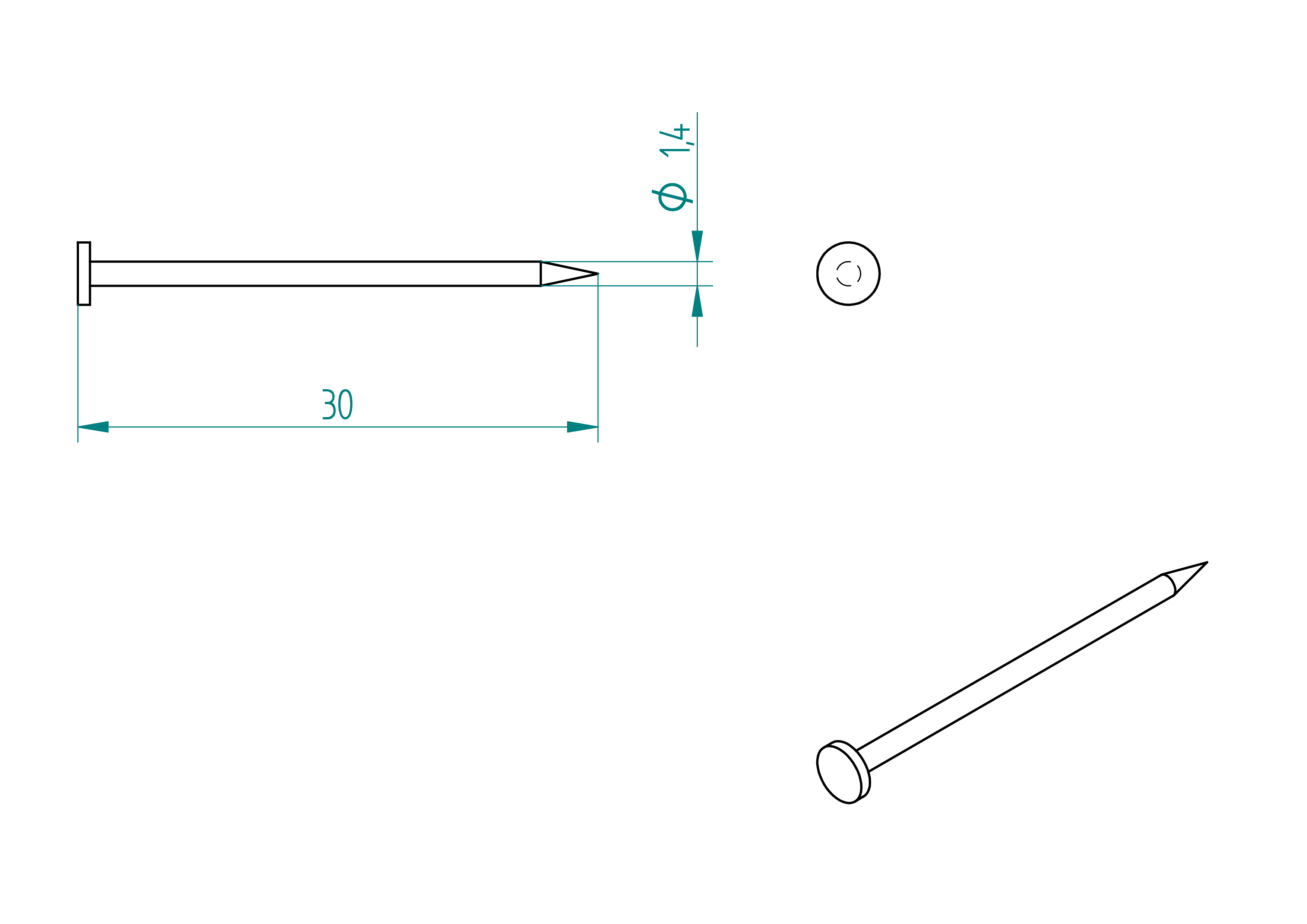
- quantity: 1 box ;
- material: steel ;
- provider: ironmongery ;
- price: ?.
amidon-glue
- quantity: a bit ;
- provider: any ironmongery ;
- price: ?
Assemblies
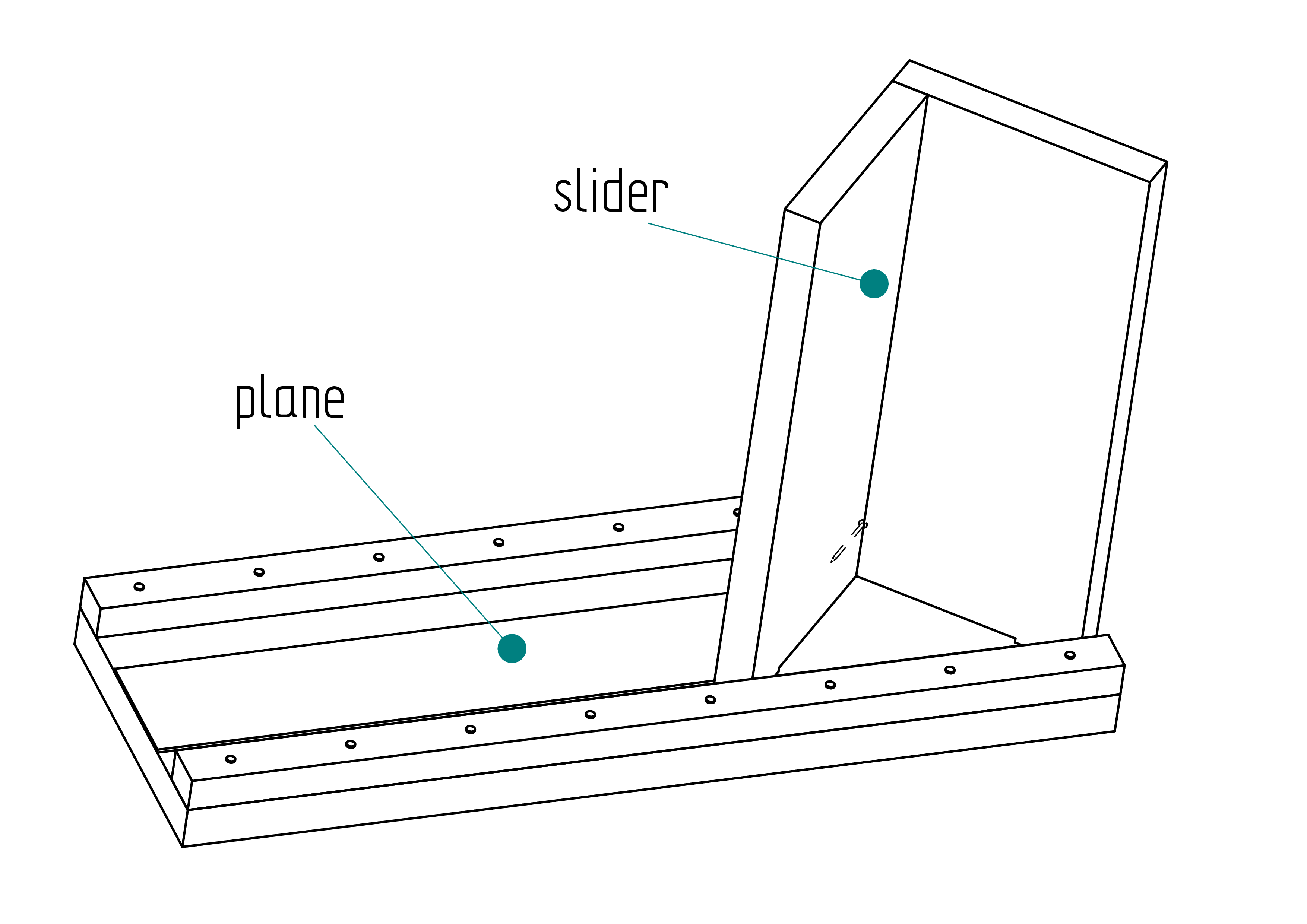
After built all the Shaped-parts and get all Normalized-parts, it's time now to assemble the sub-assemblies :
- plane ;
- slider.
Roadmap
- assemble the plane ;
- assemble the slider ;
- assemble the perpendiculator with plane and slider.
plane
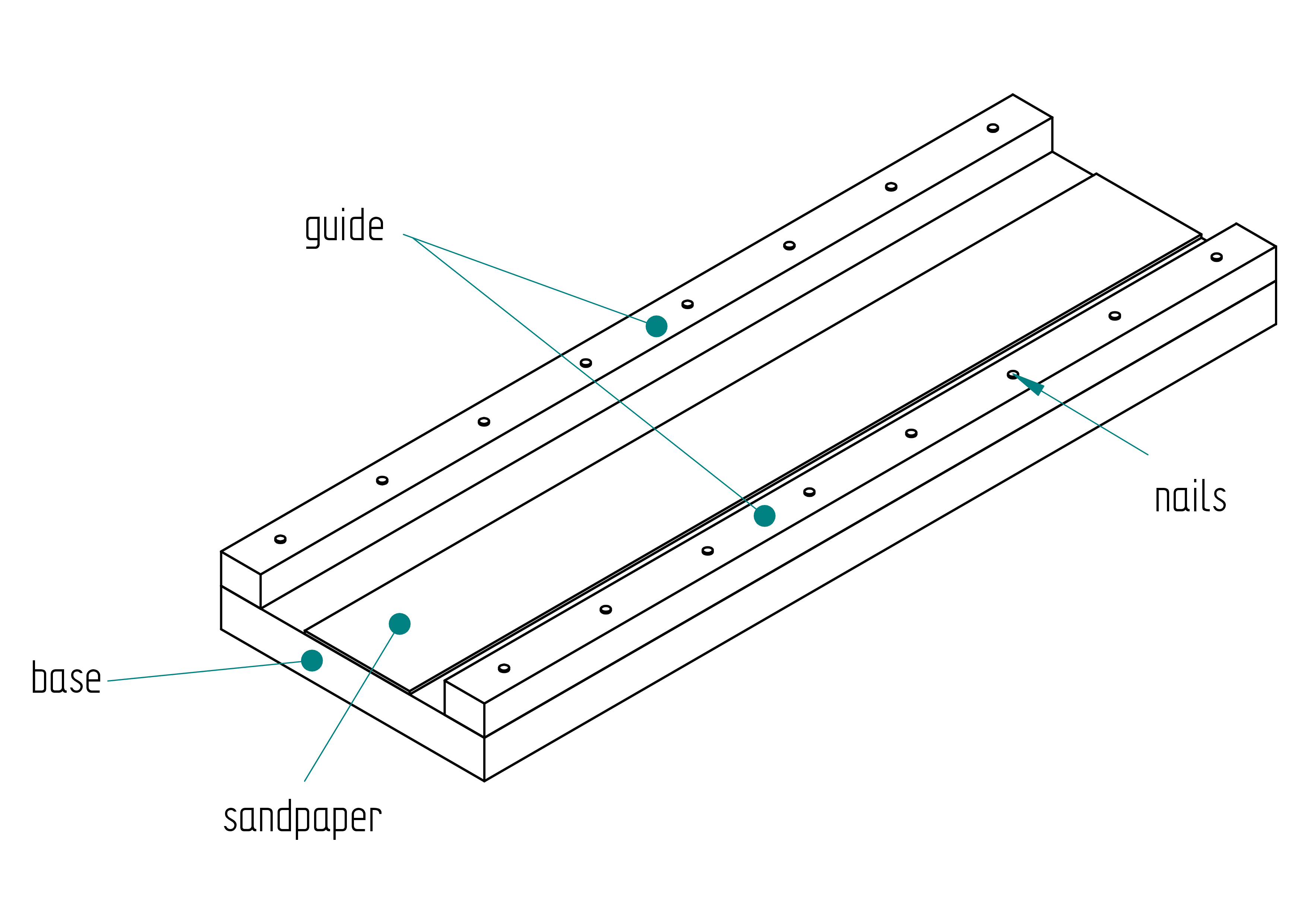
In this section we explain how to assemble the plane which is a sub-assemblie of the perpendiculator.
- with amidon glue glue the sandpaper at the right position () ;
- align the guide to the edge of the base ;
- once well aligned, clamp with two clamps ;
- put the nails in the holes of the guide ;
- hammer the nails maybe 2 or 3mm inside the base ;
- make a mark to know the direction of guide on the base ;
- remove the clamps and the guide from the base ;
- put some wooden glue on the guide ;
- then align the guide with the holes made with the nails in the base ;
- hammer the nails deep into the base to tight the guide ;
- repeat these steps for the second guide ;
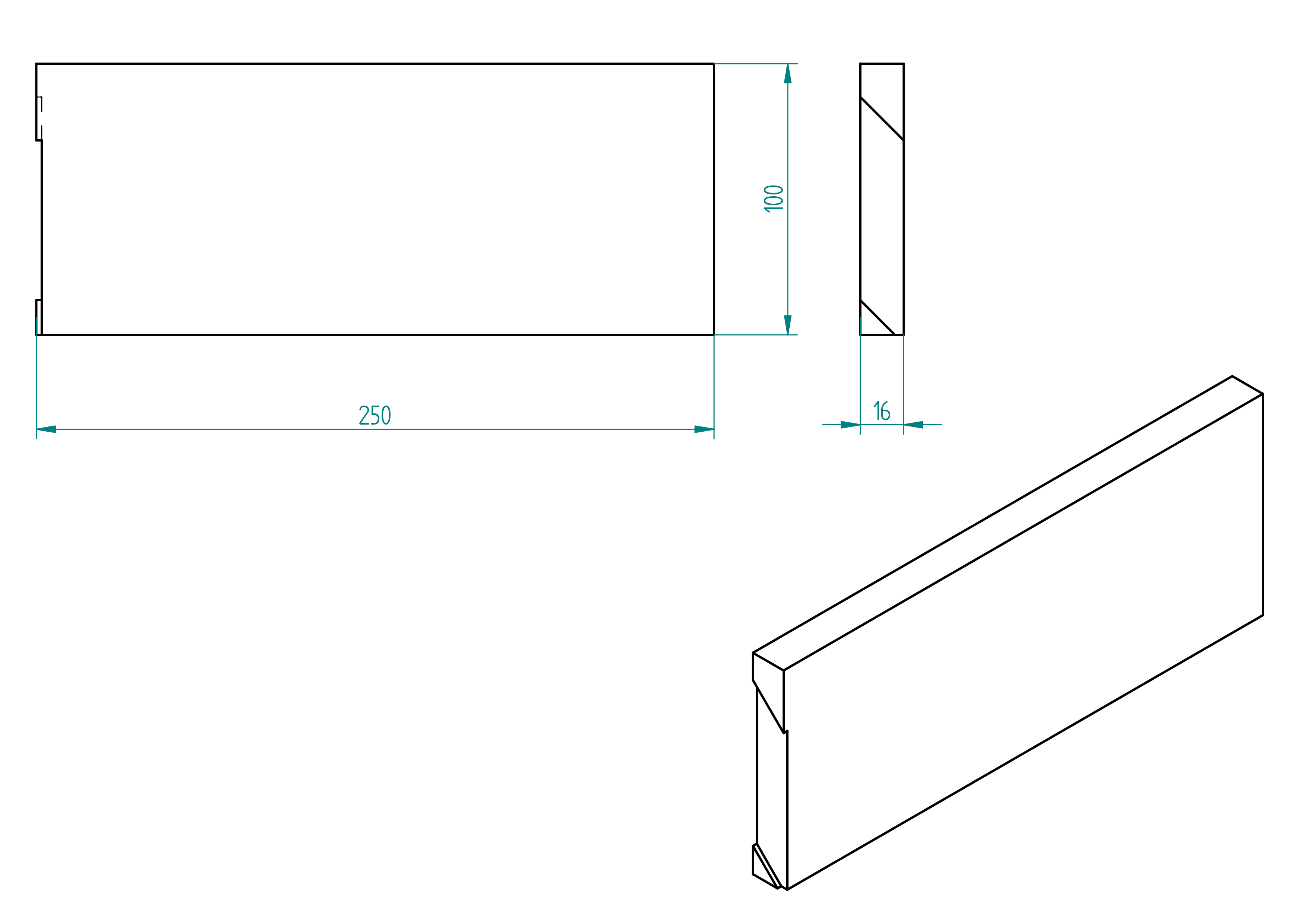
slider
In this section we explain how to assemble the slider which is a sub-assemblie of the perpendiculator.
- put the nails in the holes of face-2 ;
- align the face-2 on the face-1 ;
- press both parts with a clamp ;
- hammer the nails 3 to 4mm into the face-1 ;
- remove the clamps and unjoin face-1 and face-2 ;
- put some wooden-glue on the face-2 ;
- join both part again taking care that that the nails go into the hole of 3 to 4mm depth done at the previous point ;
- hammer the whole length of the nails so that both parts are pressed for glueing.
How to upload firmware
-
Install the Arduino IDE from
https://www.arduino.cc/en/software. -
In the Arduino IDE, go to File → Preferences, and in the ``Additional Board Manager URLs'', add:
https://raw.githubusercontent.com/espressif/arduino-esp32/\\ gh-pages/package\_esp32\_index.json -
Go to Tools → Board →> Boards Manager, search for
esp32, and install the board package byEspressif Systems. -
Connect your ESP32 board via USB and select the correct board from Tools → Board, e.g.,
ESP32 Dev Module. -
Select the correct COM port under Tools → Port.
-
Open the firmware source code from the
codedirectory. -
Click the Upload button. If it fails to connect, press and hold the BOOT button on the ESP32 during the upload process.
Attach the motor cable
This appendix explains how to attach a motor cable to a motor that
does not come with one pre-installed.
While I do not recommend purchasing a motor without a pre-installed
cable—since the final result often appears less professional. This
method can be useful if a longer cable is required than what is
typically provided.
A detailed walkthrough of the steps below is available in the following video :\
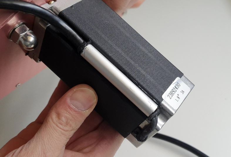
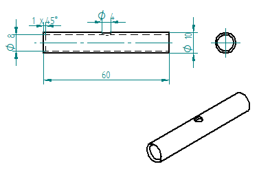
- Make an aluminium tube with the following dimensions: 10/8 × 60 mm ().
- Unpack and test the motor. Connect the 4 wires to the power unit and make the motor rotate.
This step is essential before proceeding with the remaining instructions.
Remark: There are two types of motors: 3 A and 4.2 A.
Each type uses different wire color codes. Depending on your motor's
current rating, cut the wires as follows: (See also
Figure ,
page )
- Motor 3 A:
- Red wire: 47 mm
- Yellow wire: 57 mm
- Blue wire: 67 mm
- Green wire: 77 mm
- Motor 4.2 A:
- Red wire: 47 mm
- Green wire: 57 mm
- Black wire: 67 mm
- Blue wire: 77 mm
- Strip, twist, and tin-plate the motor wires over a length of 5 mm.
- Cut a piece of heat shrink tube to 37 mm and tighten it using an industrial hot air gun.
Ensure the red wire protrudes by approximately 5 mm. - Cut the 4-core silicone cable to a length of 2.2 m.
- Strip the outer sheath of the 4-core silicone cable to a length of 45 mm.
- Cut the inner wires of the 4-core silicone cable to the following lengths:
- Red: 40 mm
- Yellow: 30 mm
- Black: 20 mm
- Green: 10 mm
- Strip, twist, and tin-plate each of the inner wires to a length of 5 mm.
- Cut four pieces of heat shrink tube, each 13 mm long.
- Slide the 13 mm heat shrink tubes and the cable holder tube onto the silicone cable.
Pay attention to the orientation of the chamfer (1 × 45°). Then solder the connections. - Degrease the cable holder tube, the silicone cable, and the motor using acetone.
**Warning for :
If the motor is not yet fixed to the machine, remember to insert the screw into the motor’s threaded hole (see picture below).
12. Inject silicone glue into the 4 mm diameter hole until it exits from both sides of the cable holder tube.
Use any excess to seal around the motor groove where the M5 × 40 hex-head Allen screw is located.
Rotate the cable holder so the injection hole is hidden against the motor.
Install a cable tie around the silicone cable, and attach the cable
holder using the clamp ().
If needed, inject more glue at the chamfered end of the tube and apply
silicone on the motor to cover any wires that extend slightly beyond
the heat shrink tubing.
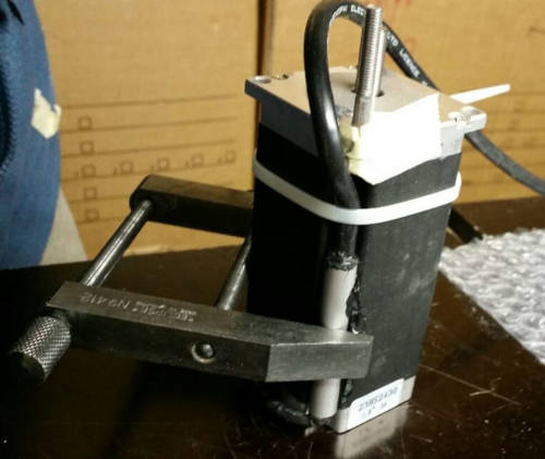
- Allow the assembly to harden. Clean up and remove any glue residue or excess from the tube.